Ferrite-Based Coaxial Isolator: How It Works






2026-07-20 16:01:31
A coaxial isolator is an inactive device made of ferrite materials and coaxial connections that works by Faraday's principles to let radio waves (RF) move forward with little loss while collecting energy that is going backwards. Modern RF systems have a big problem with reflections caused by impedance mismatches. This basic feature fixes that problem. When antennas or loads don't perfectly match the impedance of the transmission line, energy is reflected back into the line and causes standing waves and voltage spikes that can damage high-power amplifiers and local oscillators. These isolators keep the system stable and keep expensive parts from getting permanently damaged by sending this harmful reflected energy into an internal termination load. Coaxial isolators based on ferrite have become very important in RF and microwave systems used in radar, test instruments, and telecommunications. Engineers and procurement managers who are in charge of 5G infrastructure, satellite communications, and security systems depend on these parts to keep signals strong and devices lasting a long time. The effects on the economy go beyond the cost of individual parts. System downtime, replacing equipment, and efficiency loss all cost a lot of money. Figuring out how these isolators work and picking the right specs has a direct effect on how well they work, how much they cost to maintain, and how reliable the system is. This guide is designed to help B2B decision-makers who are trying to figure out how to buy RF components by giving them basic information and useful tips.
What Is a Ferrite-Based Coaxial Isolator?
Core Working Principle
Ferrite-based coaxial isolators use the gyromagnetic qualities of ferrite materials when they are magnetically biased to send signals in a way that doesn't return them. When an outside magnetic field saturates the ferrite element, electromagnetic waves move at different speeds depending on which way they are traveling. Forward signals go through with an insertion loss of less than 0.5 dB, but backwards signals run into high resistance and are sent to a matching resistive load, where the energy is lost as heat. Circulators are basically three-port devices, with the third port ending inside an isolator. This process is very different from circulators.
Technical Architecture and Design
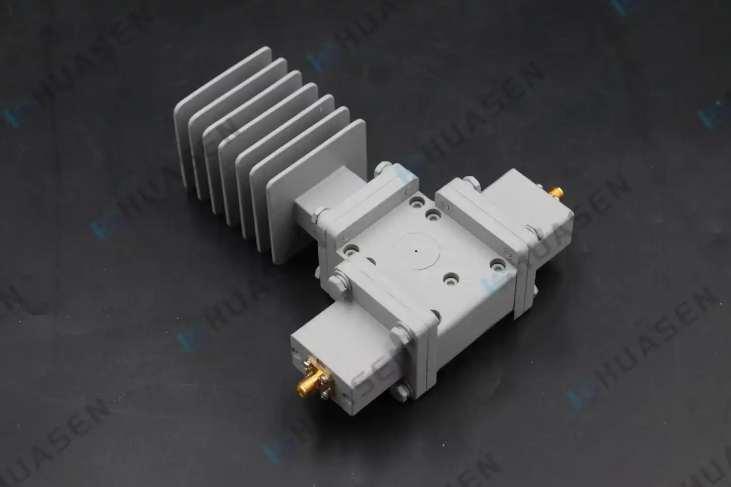
The inner structure is made up of a ferrite disc inside a coaxial transmission line and permanent magnets all around it to provide the necessary DC magnetic field. The frequency response and temperature stability of a ferrite element depend on the material it is made of, which is usually yttrium iron garnet (YIG) or lithium ferrite. Nickel-plated aluminium or steel shielding is used in the construction of housing to stop magnetic field leakage and make the structure strong. You can choose from SMA, N-type, TNC, and 2.92 mm connectors, depending on your frequency and power handling needs.
Critical Performance Parameters
The isolation rating tells you how well the device can block backwards signals. For high-end units, the number should be 20dB to 25dB or higher. Insertion loss measures how much forward signal reduction there is, which has a direct effect on the noise figure and system efficiency in receiver chains. VSWR, or Voltage Standing Wave Ratio, shows how well the impedance matches. Values below 1.25:1 are considered excellent. Power handling is broken down into two parts: forward power capacity and reverse power rating. Forward power capacity is the most continuous wave (CW) power that the device can handle, and reverse power rating is limited by the internal termination resistor's ability to remove heat. When you understand these factors, you can match specifications more accurately when buying.
Key Applications and Advantages of Ferrite-Based Coaxial Isolators
Industry-Specific Deployment Scenarios
The biggest area of use for coaxial isolators is in wireless telecommunications infrastructure. They keep power amplifiers in 5G massive MIMO active antenna units (AAUs) from losing their tuning because of ice buildup, physical damage, or changes in impedance. Isolators are used in transmit/receive modules of radar systems to keep frequency pulling from happening in voltage-controlled oscillators and to protect sensitive receiver chains from high-power transmit leakage. These parts are used in maritime and satellite communication terminals to keep the link stable in rough environments and when the impedance changes.
Test and measurement labs use external isolators to keep Vector Network Analysers (VNAs) and signal sources safe from devices being tested that reflect a lot of light. The isolator keeps the source's resistance at 50 ohms, which keeps measurements accurate and keeps expensive test port electronics from getting damaged. Isolators are used in broadcasting systems to keep the transmitter finals safe from antenna system echoes when it's raining or when work is being done.
Comparative Advantages Over Alternative Technologies
Comparing coaxial versions to waveguide isolators, they are much better in terms of size, weight, and connection options. Waveguide parts need very tight mechanical tolerances and take up a lot more space, so they can't be used in modern small systems. When compared to circulators that are used in isolation mode, specialised isolators work better because the internal termination is already tuned for the best absorption. The all-aluminium construction of high-quality units is better at removing heat than plastic-bodied alternatives, which lets them handle more power in smaller spaces. One more benefit is that coaxial isolators are usually 30–40% cheaper than waveguide systems that do the same thing electrically and don't lose any performance.
Types and Selection Criteria of Coaxial Isolators
Frequency Band Classification
Isolators that work best with certain frequency ranges are needed for different tasks. Older gadgets that send data and lower-level wireless networks use VHF and UHF types (0.3 to 1 GHz). Base stations for mobile phones that work with 4G LTE and lower 5G frequency ranges use a lot of L-band and S-band isolators (1–4 GHz). Between 4 and 12 GHz, the C-band and X-band bands are used by microwave point-to-point links, radar systems, and satellite uplinks. Isolators for millimetre waves that work above 26 GHz are useful for new 5G operations and some security tasks. Higher-order mode transmission, on the other hand, needs precise links, such as 2.92 mm or 2.4 mm types.
Power Handling Categories
The choice of coaxial isolator power rating is directly related to the needs of the application and the level of failure risk that can be tolerated. Isolators that handle 10 to 50 watts of power are good for protecting receivers, testing equipment, and signal distribution networks where reflected power is low. Medium-power units with 100 to 200-watt ratings are usually used to protect base station power amplifiers and for moderate-power broadcast tasks. Broadcast transmitters, military radar systems, and industrial RF heating equipment are all demanding environments that need high-power isolators that are more than 300 watts. Pay close attention to the reverse power specification—this number usually goes 50–70% below the forward power capacity because of temperature limits in the internal load.
Environmental and Mechanical Considerations
Coaxial is influenced by the temperature range it works in. Stable gadget operation and the ferrite magnets of the isolator. Commercial units can work from -40°C to +85°C, and special versions for use on planes and in security can work from -55°C to +125°C. It's very important for mobile platforms to have specs that say they can handle vibration and shock. For planes, ships, drones, and vehicle-mounted systems, you need devices that meet MIL-STD-810 testing standards. It is important to make sure that the mounting links and actual sizes fit in the room that you have available, especially in equipment racks or boxes that are small and crowded. When the connection gender and thread type are compatible, there are no more delays in merging or speed loss from adapters.
Table 1: Coaxial Isolator Selection Matrix by Application
| Application Domain | Frequency Range | Power Rating | Key Requirements | Typical Connector |
|---|---|---|---|---|
| 5G Base Station | 3.3-3.8 GHz | 150-200W | Low insertion loss, high isolation | N-Type Female |
| Satellite Terminal | 10.7-12.75 GHz | 20-50W | Temperature stability, low VSWR | SMA Female |
| Test Equipment | 0.5-18 GHz | 10-30W | Broadband, ultra-low loss | SMA or K-Type |
| Radar T/R Module | 8-12 GHz | 50-100W | Compact size, MIL-STD compliance | SMA or 2.92mm |
| Broadcast Transmitter | 0.5-1.0 GHz | 300-500W | High reverse power handling | 7/8" EIA Flange |
Huasen Microwave Coaxial Isolator Product Specifications
Design Excellence and Performance Characteristics
Huasen Microwave's Coaxial Isolator product line demonstrates engineering expertise accumulated since 1993, addressing the demanding requirements of modern RF infrastructure. Our isolators cover frequency bands from 0.33 GHz to 3.1 GHz, strategically encompassing the majority of cellular communication frequencies, including legacy systems through advanced 5G deployments. The all-aluminium casing design represents a deliberate engineering choice prioritising thermal management and mechanical integrity over cost reduction. This construction approach enables efficient heat transfer from the internal ferrite assembly and termination load to the external environment, supporting continuous high-power operation without performance degradation.
High isolation performance prevents signal reflection and interference that would otherwise compromise system stability. The devices achieve isolation specifications exceeding 20dB across operational bandwidths, effectively protecting upstream power amplifiers from destructive reflected energy. Average power handling up to 200 watts positions these isolators appropriately for base station transmitter protection, point-to-point radio systems, and medium-power broadcast applications. Temperature coefficient optimisation ensures stable centre frequency and consistent isolation across the -40°C to +85°C operating range, addressing outdoor installation environments from arctic to desert conditions.
Table 2: Huasen Microwave Coaxial Isolator Technical Parameters
| Parameter | Specification | Notes |
|---|---|---|
| Frequency Coverage | 0.33-3.1 GHz | Multiple band options available |
| Isolation | ≥20 dB | Typical 22-25 dB across band |
| Insertion Loss | ≤0.4 dB | Frequency dependent |
| VSWR | ≤1.25:1 | Both ports, full temperature range |
| Forward Power (CW) | 200W Average | Altitude and cooling dependent |
| Reverse Power | 30W Maximum | Continuous, into matched load |
| Operating Temperature | -40°C to +85°C | Extended range available |
| Housing Material | Aluminum Alloy | Anodized finish, RoHS compliant |
| Connector Types | N-Type, SMA | Custom options upon request |
Application-Driven Customization Capabilities
Recognising that standard catalogue products rarely satisfy all system requirements, Huasen Microwave maintains extensive customisation capabilities. Frequency band optimisation allows precise tuning to customer-specified centre frequencies and bandwidth requirements, maximising isolation and minimising insertion loss for the actual operating frequencies. Power handling can be scaled upward through enhanced heat sinking, forced-air cooling provisions, or oversized internal terminations for applications exceeding standard ratings. Connector configurations adapt to system architecture needs—mixed-gender combinations, right-angle orientations, or specialised military connectors integrate seamlessly without requiring external adapters that would degrade performance.
Environmental hardening options for coaxial isolators address harsh deployment scenarios. Conformal coating protects against humidity and salt spray in maritime installations, while enhanced shock mounting accommodates mobile platforms subjected to continuous vibration. These customisations stem from direct collaboration between customer engineering teams and Huasen Microwave's technical staff, ensuring delivered products precisely match application requirements without unnecessary over-specification.
Conclusion
Ferrite-based coaxial isolators represent essential protective and performance-enhancing components in modern RF and microwave systems. Their ability to prevent destructive reflected power from damaging expensive amplifiers while maintaining signal integrity makes them indispensable across telecommunications infrastructure, radar installations, test equipment, and aerospace platforms. Understanding the working principles, performance parameters, and selection criteria empowers engineers and procurement professionals to specify appropriate devices matching application requirements without unnecessary over-specification or capability gaps. The evolution towards higher-frequency 5G deployments, increased power densities, and more compact system architectures continues to drive demand for advanced isolator designs offering superior thermal management, environmental resilience, and reliable performance. Strategic partnerships with experienced manufacturers providing customisation capabilities, comprehensive technical support, and proven quality systems deliver competitive advantages through reduced integration risk, optimised system performance, and long-term supply chain stability.
FAQ
1. What distinguishes a coaxial isolator from a circulator?
A coaxial isolator is essentially a three-port circulator with the third port internally terminated by a matched resistive load. While circulators route signals sequentially from port to port in a circular pattern, isolators convert reverse-travelling energy into heat within the termination resistor, effectively creating a two-port device with unidirectional signal flow. This design optimisation delivers superior reverse signal suppression compared to external termination approaches.
2. Why does the reverse power rating differ from the forward power capacity?
Forward-travelling power passes through the ferrite junction with minimal interaction, experiencing only insertion loss typically below 0.5 dB. Reverse power gets diverted into the internal termination load, where it dissipates entirely as heat. The reverse power rating is constrained by the wattage capacity and heat dissipation capability of this internal resistive element, typically limiting reverse handling to 30-50% of forward power ratings. Exceeding this specification causes termination, overheating, and permanent device damage.
3. How does operating temperature affect isolator performance?
Ferrite materials exhibit temperature-dependent magnetic properties approaching their Curie temperature threshold. This causes centre frequency shifts and isolation degradation at temperature extremes. Quality isolators employ temperature-compensating magnetic circuit designs and carefully selected ferrite compositions, maintaining stable performance across -40°C to +85°C ranges. Applications experiencing wider temperature excursions require specialised units with enhanced thermal compensation or active temperature control.
Partner with Huasen Microwave for Superior Coaxial Isolator Solutions
Huasen Microwave Technology stands as a trusted coaxial isolator manufacturer with three decades of engineering excellence in high-frequency microwave and millimetre-wave components. Our comprehensive isolator product line covering 0.33 GHz to 3.1 GHz delivers the high isolation, low insertion loss, and robust power handling your critical RF systems demand. The all-aluminium construction and 200-watt average power capability ensure reliable protection for base station amplifiers, radar systems, and communication infrastructure operating in demanding environments. Beyond standard catalogue offerings, our engineering team collaborates directly with customers to develop customised solutions matching exact frequency specifications, power requirements, and environmental conditions.
Reach our technical specialists at sales@huasenmicrowave.com to discuss your specific application requirements, request detailed technical datasheets with measured S-parameter data, or obtain volume pricing quotations. We provide comprehensive pre-sale engineering support, including thermal analysis, system integration guidance, and sample evaluation programs, reducing your project risk. With certifications spanning ISO quality standards and RoHS environmental compliance, plus a stable supply chain built over 30 years, Huasen Microwave delivers the reliability and partnership your organization requires for successful RF system deployments.
References
1. Linkhart, Douglas K. Microwave Circulator Design, Second Edition. Artech House Publishers, 2014.
2. Pozar, David M. Microwave Engineering, Fourth Edition. John Wiley & Sons, 2011.
3. Helszajn, Joseph. The Stripline Circulator: Theory and Practice. IEEE Press Series on Electromagnetic Wave Theory, 2008.
4. Collin, Robert E. Foundations for Microwave Engineering, Second Edition. IEEE Press, 2001.
5. Baden Fuller, A.J. Ferrites at Microwave Frequencies. IET Electromagnetic Waves Series, 1987.
6. Ishii, T.K. Handbook of Microwave Technology: Components and Devices, Volume 1. Academic Press, 1995.
Send Inquiry