How to Fix Excessive Insertion Loss in Waveguide Adapters?






2026-02-10 21:41:17
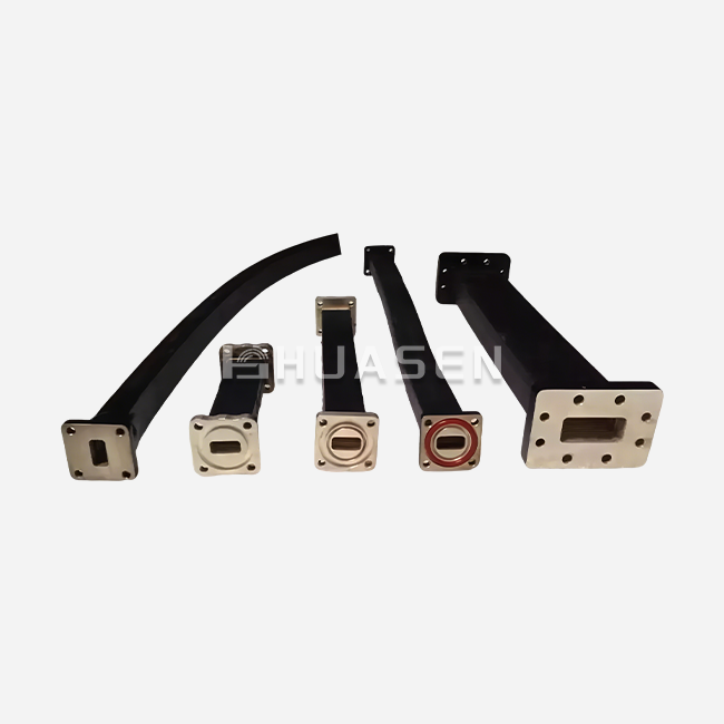
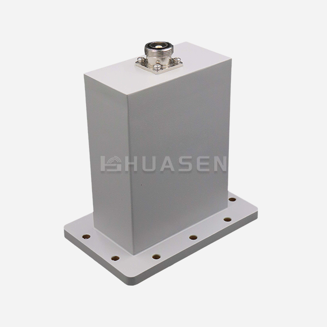
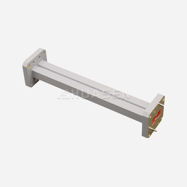
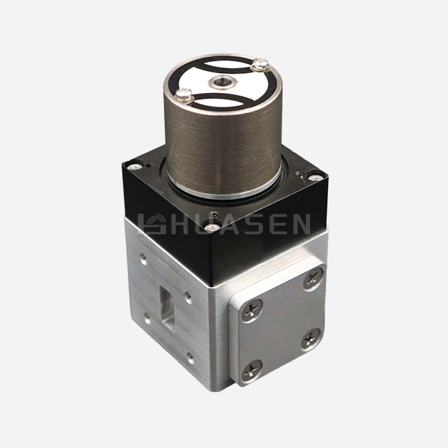
Too much insertion loss in waveguide adapters can seriously damage the purity of signals and the performance of systems in important RF and microwave applications. The answer includes a methodical diagnosis, the right way to install things, choosing high-quality materials, and making strategic partnerships with suppliers. To fix insertion loss, you need to know what causes it, like impedance mismatches, bad connection alignment, contamination, and low-quality parts. Professional-grade waveguide adapters with tight manufacturing tolerances, gold-plated surfaces, and certified performance standards keep signals from degrading a lot and make sure they work reliably in harsh conditions.
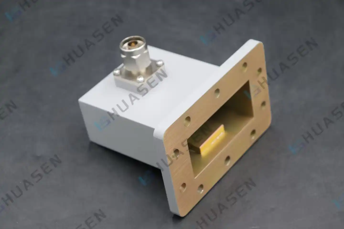
Understanding Excessive Insertion Loss in Waveguide Adapters
Insertion loss is the signal power loss that happens when electromagnetic energy goes through waveguide components. This has a direct effect on how well microwave and RF systems work. This effect is especially important in high-frequency settings, where even small power losses can lead to big problems with how well the system works.
Defining Acceptable Insertion Loss Values
Professional radio frequency (RF) systems usually work within certain limits of insertion loss, which change for different frequency bands and uses. Standard rectangular waveguide adapters usually have insertion losses between 0.05 dB and 0.2 dB across the frequency bands they work with. To keep signals clear and transmission efficiency high, 5G infrastructure, satellite communications, and radar systems need very low insertion loss. Industry standards say that insertion loss measurements should stay the same even when temperature changes and mechanical stress levels change. For high-performance waveguide components to work properly, their electrical properties must stay stable over time. This is especially important for outdoor locations where environmental factors can change how the components behave.
Common Causes of Excessive Insertion Loss
Material decay is one of the main reasons why insertion loss is high in waveguide systems. Surface rust, corrosion, and contamination cause resistive losses that turn signal energy into heat instead of letting it be sent efficiently. Impedance mismatches happen when manufacturing tolerances aren't met, reflecting parts of the signal being sent and lowering forward power transfer. Flange misalignment is another important factor that affects insertion loss performance. If you don't connect the waveguide parts correctly, air gaps or mechanical stress can cause the gearbox path break. These breaks make standing wave patterns that increase reflected power and lower the overall efficiency of the system. Environmental factors like moisture entering, temperature cycling, and mechanical vibration damage parts over time. In marine settings, salt spray speeds up the corrosion process, and the cycling of heat expansion and contraction can loosen connections and change important dimensions.
Diagnosing the Root Causes of Excessive Insertion Loss
For troubleshooting to work, it's important to start with thorough visual inspection methods that look for clear signs of component wear or installation problems. This methodical approach helps technicians quickly find problems and put in place focused fixes that get things back to working at their best.
Visual Inspection Techniques
The flange surfaces, gasket conditions, and connector alignment signs should be the main focus of the physical examination. Corrosion, pitting, or discolouration on joining surfaces are signs of damage to the environment that needs to be fixed right away. Checking for contamination means looking for foreign materials, moisture buildup, waveguide to coaxial adapter, or oxidation products that get in the way of electrical contact. Gasket compression marks show if the right torque specifications were used during installation, while misaligned bolt patterns show possible mechanical stress problems. At millimeter-wave frequencies, even tiny particles can cause a lot of insertion loss. This is why thorough cleaning is necessary to keep performance standards.
Advanced Measurement Approaches
Testing with a network analyzer gives you numbers that show how insertion loss behaves across a range of operating frequencies. Swept frequency measurements find resonance problems or bandwidth limits that might not be clear from basic power measurements. Return loss analysis helps tell the difference between problems caused by resistance losses and reflections. Technicians can see how parts are wearing out over time by comparing their baseline performance. Setting reference measures during the initial installation makes ongoing maintenance programs more useful. Recording the testing environment's conditions makes sure that measurement methods are always the same and that trend analysis is accurate. Testing at a controlled temperature shows how thermal coefficient effects affect insertion loss stability. Components that are very sensitive to temperature changes may need to be protected from the environment or replaced with ones that are less sensitive to temperature changes.
Practical Steps to Fix and Reduce Insertion Loss
Using high-quality parts and following systematic maintenance methods can greatly lower insertion loss and increase service life. These tried-and-true methods fix both short-term speed problems and long-term reliability issues.
Installation Best Practices
Proper torque application ensures optimal electrical contact without overstressing mechanical components. Torque specifications typically range from 25 to 40 foot-pounds for standard rectangular waveguide flanges, depending on flange size and material composition. Using calibrated torque wrenches prevents inconsistent connections that contribute to insertion loss variations. Surfacepreparation involves thorough cleaning with appropriate solvents and lint-free materials before assembly. Contamination removal requires specific techniques that avoid scratching or damaging critical surfaces. Applying thin layers of conductive grease on flange interfaces improves electrical contact and provides environmental protection. Alignment verification confirms that waveguide sections mate properly without mechanical stress or angular misalignment. Using precision alignment tools during installation prevents long-term performance degradation caused by improper assembly techniques.
Premium Material Selection and Design Features
Advanced material technologies offer substantial improvements in insertion loss performance compared to standard alternatives. These innovations address fundamental loss mechanisms while providing enhanced environmental resistance. Gold plating represents the industry standard for high-performance waveguide components due to its exceptional conductivity and corrosion resistance. The precious metal coating maintains stable electrical properties across wide temperature ranges while preventing oxidation that degrades conventional metal surfaces. Silver plating offers similar conductivity benefits at reduced cost but requires additional environmental protection in corrosive atmospheres. Precision manufacturing tolerances ensure consistent impedance characteristics that minimize reflection-based losses. Computer-controlled machining processes achieve dimensional accuracies within micrometers, eliminating the discontinuities that create standing wave patterns. Surface finish specifications below 32 microinches RMS reduce conductor losses at millimeter-wave frequencies. Enhanced gasket designs provide improved environmental sealing while maintaining optimal electrical performance. Conductive elastomer materials combine mechanical compliance with low-resistance electrical paths, ensuring reliable operation under thermal cycling conditions.
Calibrated Testing and Maintenance Protocols
Regular performance verification using calibrated measurement equipment identifies developing problems before they impact system operation. Monthly insertion loss measurements provide trending data that reveals gradual component degradation patterns. Immediate investigation of measurements exceeding baseline values by more than 0.1 dB prevents cascade failures in critical systems. Preventive maintenance schedules should include detailed cleaning procedures, torque verification, waveguide to coaxial adapter,and environmental protection assessments. Quarterly inspections in harsh environments help identify components requiring replacement before failure occurs.
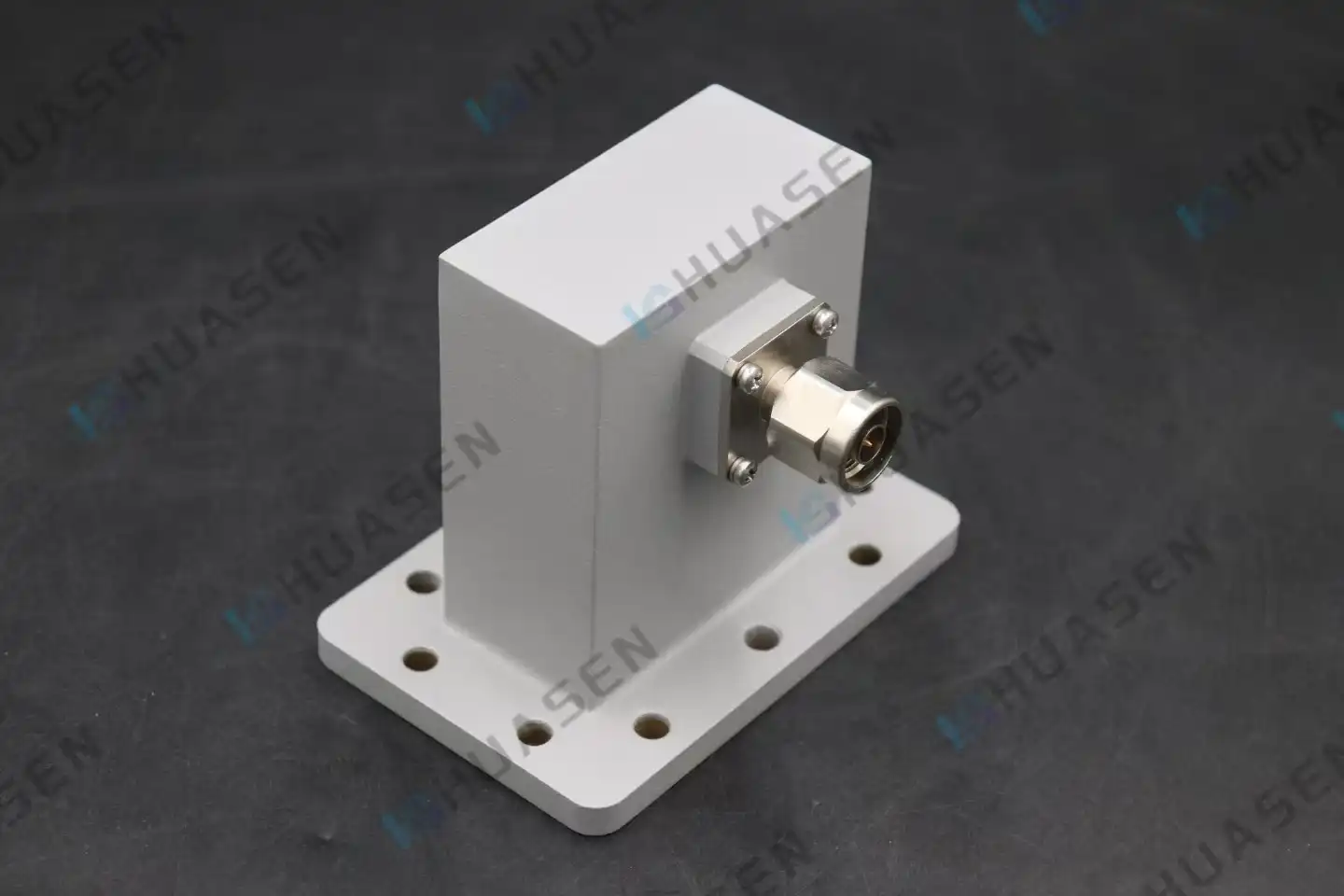
Case Studies: Successful Reduction of Insertion Loss
Real-world implementation examples demonstrate the effectiveness of systematic approaches to insertion loss reduction. These documented cases provide valuable insights for procurement professionals and system engineers facing similar challenges.
Industrial Microwave System Upgrade
A telecommunications infrastructure project experienced significant signal degradation across multiple base station installations due to incompatible waveguide adapter selections. Initial measurements revealed insertion loss values exceeding 0.8 dB per adapter, far above acceptable performance thresholds. Comprehensive system analysis identified fundamental impedance mismatches between different manufacturer components that created severe reflection losses. The mixed-vendor approach, initially intended to reduce procurement cost,s actually compromised system reliability and increased operational expenses. The solution involved standardizing on precision-manufactured adapters from a single qualified supplier, ensuring consistent electrical characteristics throughout the installation. Premium gold-plated components replaced standard alternatives, while improved installation training addressed assembly technique issues. Post-upgrade measurements confirmed insertion loss reductions to below 0.15 dB per adapter, representing a substantial improvement in signal transmission efficiency.
Satellite Communication Performance Enhancement
A maritime satellite communication system suffered from intermittent signal quality issues traced to excessive insertion loss in critical waveguide connections. Environmental exposure in salt spray conditions accelerated corrosion processes that degraded electrical performance over time. Custom adapter development addressed the unique environmental challenges while meeting stringent electrical performance requirements. Enhanced environmental sealing, corrosion-resistant materials, and improved mechanical designs provided long-term reliability in harsh maritime conditions. Collaboration with an experienced supplier enabled rapid prototyping and field testing of candidate solutions. Performance improvements included insertion loss reduction from 0.6 dB to 0.12 dB while achieving superior environmental protection ratings. The customized approach delivered both immediate performance gains and reduced maintenance requirements, ultimately loweringthe total cost of ownership despite higher initial component costs.
Selecting the Right Waveguide Adapter Supplier and Product
Strategic supplier evaluation encompasses multiple factors that influence both immediate performance and long-term operational success. Comprehensive assessment criteria ensure optimal component selection for demanding applications.
Quality and Certification Standards
Industry approvals are an objective way to prove that a product is of good quality and consistently performs well. ISO 9001 quality control systems show that a company wants to keep getting better and make sure customers are happy. As an example, military specifications like MIL-DTL-3922 set strict performance standards for demanding uses. Test data documentation shows how a component actually works in different environments. Full sets of data should have measurements of insertion loss and return loss, as well as information on how much power they can handle and the results of outdoor tests. Statistical process control data shows how consistently and reliably products are made. Warranty terms show that the maker trusts the quality of the product and protects against early failures. Providing a longer warranty shows that you care about your customers and the stability of your products. Having technical support available means that you can get help with applications at any time during the span of the product.
Supplier Evaluation Criteria
When you do a manufacturing capability review, you look at things like technical know-how, production capacity, and quality control systems. Site trips let you see for yourself how things are made, what equipment can do, and how quality control is done. Suppliers whose finances are stable can guarantee that parts will be available and that they will be able to provide ongoing support. Supply chain management skills are essential for buying in bulk and for making unique parts. When requirements or delivery dates change, flexible manufacturing methods let you respond quickly. For foreign installations, global distribution networks offer local support and lower shipping costs. Technical support services, such as design help, application guidance, and troubleshooting support, add a lot of value on top of providing basic components. Field application engineers with a lot of experience help improve system performance while lowering the risks of implementation. Training programs help customers get better at using technology and make installations better.
Custom Versus Standard Product Considerations
For common uses, standard waveguide adapters are readily available, have been shown to work well, and are priced competitively. There is trust in the reliability and performance characteristics because of the extensive testing and field deployment history. Large-scale deployments can be done at low cost thanks to the economics of mass production. Custom adapter development is helpful when standard goods can't meet specific performance, environmental, or mechanical needs. For some uses, you may need frequency ranges, power handling capabilities, or environmental protection levels that aren't available in standard products. Custom solutions can improve performance for certain system architectures while getting rid of the problems that come with general-purpose designs. When choosing between standard and custom products, you should think about the total cost of ownership, which includes the cost of buying them, how hard they are to install, how much maintenance they need, and how much they improve performance. Custom development timelines and minimum order amounts can change how projects are planned and how inventory is managed.
Conclusion
To get the best system performance,you need to carefully check for excessive insertion loss in waveguide adapters, use professional-grade parts, and form smart partnerships with suppliers. Figuring out the reasons, like impedance mismatches, environmental damage, waveguide adapters,and installation problems, lets you come up with specific solutions that fix the signal integrity and improve transmission efficiency. High-quality materials, precise manufacturing, and following the right upkeep procedures ensure long-term dependability while keeping costs low. The case studies show that spending more on high-quality parts and skilled installation leads to measurable performance gains that make up for the higher initial costs through less maintenance and more reliable systems.
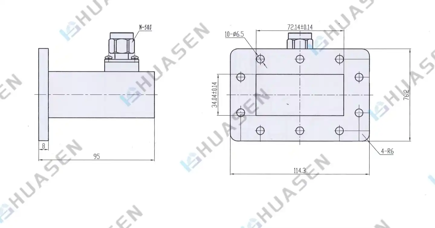
FAQ
1. How often should waveguide adapters be inspected for insertion loss degradation?
Monthly performance verification measurements provide adequate monitoring for most applications, while harsh environmental conditions may require more frequent assessment. Quarterly detailed inspections, including torque verification and cleaning,g help prevent serious degradation issues.
2. What role does installation quality play compared to adapter material selection?
Both factors significantly influence insertion loss performance, but proper installation techniques can optimize even standard components while poor installation compromises premium materials. Professional installation training and calibrated tools ensure consistent results regardless of component grade.
3. What are typical lead times for custom waveguide adapter orders?
Standard lead times range from 1 to 2 weeks for custom waveguide adapter development, depending on complexity and testing requirements. Rush orders may be accommodated with expedited manufacturing schedules, though additional costs typically apply for accelerated delivery.
Partner with Huasen Microwave for Superior Waveguide Solutions
Huasen Microwave Technology combines three decades of microwave engineering expertise with advanced manufacturing capabilities to deliver waveguide adapters that minimize insertion loss and maximize system performance. Our ISO-certified production facility produces precision components with gold-plated surfaces, superior environmental protection, and documented performance characteristics that exceed industry standards. As a trusted waveguide adapters manufacturer, we provide comprehensive technical support, custom design services, and reliable delivery schedules for critical applications across telecommunications, aerospace, and defense sectors. Contact our engineering team at sales@huasenmicrowave.com to discuss your specific requirements and discover how our proven solutions can optimize your system efficiency while reducing operational costs.
References
1. Pozar, David M. "Microwave Engineering, Fourth Edition." John Wiley & Sons, 2012.
2. Marcuvitz, Nathan. "Waveguide Handbook." McGraw-Hill Book Company, 1951.
3. Collin, Robert E. "Foundations for Microwave Engineering,g Second Edition." McGraw-Hill, 1992.
4. Ragan, Gerald L. "Microwave Transmission Circuits." McGraw-Hill Book Company, 1948.
5. Institute of Electrical and Electronics Engineers. "IEEE Standard for Rectangular Metallic Waveguides and Their Interfaces for Frequencies of 110 GHz and Above." IEEE Std 1785-2013.
6. Harvey, A.F. "Microwave Engineering." Academic Press, 1963.
Send Inquiry