How Does a Corrugated Conical Horn Antenna Achieve Low Sidelobes?






2026-07-27 10:02:18
When we examine modern microwave and millimeter-wave antenna systems, one question consistently surfaces among engineers and procurement specialists: how does a corrugated conical horn antenna achieve such remarkably low sidelobes? The answer lies in the device's unique internal geometry. Precision-machined circumferential grooves or corrugations along the interior walls support the propagation of a balanced HE11 hybrid mode, which equalizes the electric and magnetic field distributions. This symmetry creates a rotationally uniform radiation pattern with minimal off-axis energy leakage, effectively suppressing sidelobes to levels often exceeding 35 dB below the main beam—critical for applications demanding clean, interference-free signals.
Understanding the Challenge: Why Are Low Sidelobes Critical in Horn Antennas?
Sidelobes are unwanted waves that come from antennas that are not in the main beam. In real-world systems, these off-axis leaks make operations very difficult. They pick up background noise, make false targets in radar applications, and lower the signal-to-noise ratio in communication links. When your satellite ground station sends signals to a parabolic reflector, sidelobe energy that leaks past the dish's edges picks up thermal noise from the warm Earth, which directly hurts the G/T performance of your system.
There are problems with the E-plane and H-plane radiation patterns of traditional pyramidal and conical horns with smooth walls. Because of this astigmatism, circular beams with high sidelobe levels are made, usually between -15 dB and -20 dB. These performance limits cause the system to degrade in ways that can be measured for mission-critical uses in 5G backup lines, radar systems on aeroplanes, or communications in deep space. When purchasing antenna parts, teams need to keep in mind that sidelobe suppression has a direct effect on installation costs, since bad sidelobe performance usually calls for more protection, bigger exclusion zones, or more frequent calibration intervals.
Impact on System Performance
High sidelobes have effects that go beyond simple interference. High sidelobe levels make electronic defenses and communication security systems more vulnerable to signal jamming and interception. Cross-channel interference happens in maritime communication networks that work in crowded spectrum areas when antennas don't control their sidelobes well. To get accurate measurement data, testing labs that evaluate RF components need antennas with stable and predictable sidelobe characteristics. This means that choosing the right antenna is one of the most important decisions that affects the validity of all subsequent test results.
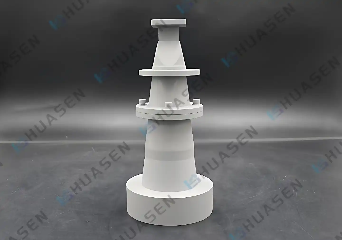
The Design Principles Behind Corrugated Conical Horn Antennas
This type of feed horn is unique because of the way its internal corrugation geometry is designed. Each seam acts as a quarter-wave or half-wave reactance surface that changes the conditions for electromagnetic waves to move. Smooth walls let different TE and TM modes move at different phase speeds. The corrugated conical horn antenna structure, on the other hand, causes these modes to move at the same speed, which lets them join coherently into the HE11 hybrid mode.
This hybrid mode has some amazing features. The horizontal electric and magnetic fields stay almost exactly where they are in space, creating a radiation pattern that is symmetrical around a circle. The beamwidth in the E-plane is very close to matching the beamwidth in the H-plane. At -15 dB, the beam equalization error is usually less than ±5°. When feeding reflector antenna systems, this kind of regularity is very important because uneven lighting leads to losses in cross-polarization and aperture efficiency.
Frequency Scalability and Bandwidth Performance
Modern designs can work with frequencies ranging from 1.76 GHz to 300 GHz, which is a very wide range. These frequencies are used for a wide range of things, from cellular infrastructure to millimeter-wave radar. The corrugation depth and spacing have a big effect on the bandwidth. In standard setups, VSWR values for octave bandwidths are less than 1.30 across the whole spectrum, and for optimized narrowband versions, they are less than 1.06. This impedance matching makes sure that the waveguide transmission lines send the most power to free-space radiation while minimizing insertion loss. This is a very important factor when every tenth of a decibel affects link budget estimates.
These devices can work with high-performance broadband feed systems and offset feed configurations thanks to their large-angle horn geometry and precise corrugated slot structures. The phase center stability stays the same across all operational bandwidths. This lets system designers set the focal point in a predictable place in both Cassegrain and Gregorian reflector configurations.
Table 1: Key Performance Specifications
| Parameter | Specification | Application Benefit |
|---|---|---|
| Frequency Range | From 1.76 GHz to 300 GHz | Includes radar, cell phone, and satellite bands |
| VSWR (Full Bandwidth) | 1.30 | Low power loss from reflections, high power transfer |
| VSWR (Narrowband) | <1.06 | Very little signal loss |
| Beam Equalization Error | ±5° at -15 dB | Light that shines evenly on mirrors |
| Cross-Polarization Isolation | >35 dB | Keeps signal disturbance at bay |
| Waveguide Interface | 2.38 mm to 114.58 mm | Standard systems can use it. |
Manufacturing Precision Requirements
To get these levels of performance, corrugated conical horn antenna manufacturing tolerances must be very tight. To keep mode purity, the depth of the corrugation must be kept within ±0.01 mm. When these limits are crossed, the delicate field balance is upset, which lets higher-order modes mess up the radiation pattern and make sidelobes bigger. The complex internal geometries that are needed can be made with advanced CNC turning and electroforming processes, but the unit costs are higher than with simple castings. When purchasing these parts, procurement professionals should check to see if the supplier can do precision machining and quality inspection. This is because the performance directly depends on the manufacturing expertise.
Comparing Corrugated Conical Horn Antennas with Other Horn Types
Smooth cylindrical horns are easy to use and don't cost much, but they make beams that are very astigmatic. The E-plane beamwidth is very different from the H-plane beamwidth, making an irregular pattern that can't be used for reflector feeds that need circular symmetry. Pyramidal horns have a modest gain and a small size, but they have sidelobe levels of about -18 dB, which is too high for uses that need strict interference control.
Sectoral horns send out fan-shaped beams that are useful in some coverage situations, but they aren't flexible enough for satellite ground stations or small antenna test areas. If you need to measure the radar cross-section on stealth platforms as part of the system requirements, you must use a corrugated conical horn antenna with a clean Gaussian beam profile and a stable phase center. They can make uniform quiet zones in CATR buildings that can't be done with other horn designs.
Selection Criteria for System Integrators
The decision matrix is more than just electromagnetic performance. In aerospace applications, like on drones and spacecraft, antenna weight and mounting options are limited by how they are built. Standard circular waveguide connections with sizes from Φ2.388 mm to Φ114.58 mm make system integration more flexible. However, to make sure the system works with current RF infrastructure, it's important to pay close attention to socket standards like SMA, K-type, and WR-series waveguide flanges.
When base station front-end systems and maritime communications are set up outside, environmental ruggedness is very important. Long-term dependability is based on how well it can handle changes in temperature, pressure, and rust. Suppliers who offer parts that meet MIL-STD-810 environmental standards and RoHS certification take care of both performance durability and regulatory compliance, which lowers the total cost of ownership even though the parts cost more at first.
Table 2: Horn Antenna Performance Comparison
| Antenna Type | Sidelobe Level | Cross-Pol | Beam Symmetry | Typical Application |
|---|---|---|---|---|
| Smooth Conical | -18 to -15 dB | Moderate | Poor | General-purpose feeds |
| Pyramidal | –18dB | Moderate | Elliptical | Small installations |
| Sectoral | -15 dB | High | Fan-shaped | Applications for coverage |
| Corrugated Conical | <-35 dB | >35 dB | Circular | Precision feeds, testing |
Real-World Applications and Benefits of Corrugated Conical Horn Antennas
Earth stations that use satellite transmission depend on these feed horns to light up parabolic mirrors as efficiently as possible. The symmetric pattern makes sure that the edges are evenly lit, which maximises aperture efficiency. At the same time, the low spillover stops ground noise pickup, which directly improves the receive system's figure of merit. Tracking interplanetary spaceships through deep space network facilities can't handle the signal loss that comes with standard feed designs; a corrugated conical horn antenna gives them the performance cushion they need.
Radio astronomy stations that look for faint waves from space need feed systems that can reject sidelobes very well. Through antenna sidelobes, background radiation from sources on Earth gets in and messes up readings of changes in the cosmic microwave background or pulsar signals. The corrugated conical horn antenna can stop off-axis reactions below -40 dB in well-designed systems, which lets them pick up signals that are orders of magnitude weaker than background noise and air noise.
Testing and Metrology Applications
These horns are used as feed sources for collimating mirrors in places that test small antennas. The radiation pattern has a clean Gaussian taper that spreads plane waves across the test area. This lets the performance of the antennas be accurately characterised without needing far-field separation distances that are too big. The quality of the feed horn directly affects how accurate measurements are of gain, pattern shape, and polarisation purity. Manufacturers of instruments and research labs that test components require corrugated conical feeds to get measurement repeatability within 0.1 dB, which isn't possible with lower-performance options.
When used for a wireless bridge, low sidelobes help point-to-point microwave links work better by blocking interference. It's easy for signals from nearby systems to weaken links in cities because the electromagnetic landscape is so crowded. When deployments are spectrally crowded, antennas with tight main beams and deep nulls between lobes keep link quality high. This means that operators don't have to coordinate as much, and installation limits are kept to a minimum.
Before putting these parts into mission-critical systems, buyers should check the qualifications of the suppliers. Consistent performance can be guaranteed by manufacturers whose quality management systems have been approved to ISO 9001 and who have shown that they follow the measurement methods in IEEE Standard 149. Getting detailed test data like full spherical pattern cuts, phase centre location curves, and VSWR traces across operating bands lets engineering teams check that system-level performance predictions are correct before ordering in large quantities.
Technical Verification and Performance Validation
Performance confirmation starts with measuring the radiation pattern in anechoic rooms that are properly set up. For far-field tests, the distance between the two devices must meet the 2D²/λ requirements, where D is the aperture width and λ is the wavelength. Facilities that can acquire circular patterns collect data across all azimuth and elevation angles. This shows sidelobe structure that might not be seen in main plane cuts alone.
Protocols for verification look at more than just sidelobe levels and many other parameters. Cross-polarisation discrimination measures how well a corrugated conical horn antenna can keep linear polarisation purity, which is very important for dual-polarisation communication systems and radar sites that process polarimetric data. Measurements of gain show that the directedness matches what was predicted theoretically based on aperture size. This proves that both the electromagnetic design and the manufacturing process worked.
Quality Assurance in Manufacturing
After the part is made, coordinate measuring tools check the internal shape to make sure that the groove depths, widths, and spacings are all correct according to the design. Measurements of surface conductivity make sure that the internal plating—usually silver or gold for millimetre-wave uses—is conducting enough to keep resistance losses to a minimum. As the frequency goes up, these losses get bigger. At 100 GHz, even a small change in the surface finish can be seen to have a real effect on efficiency.
Measurements made with a vector network analyser show the impedance properties across all operating bands. There should be less than 20 dB of return loss across the whole frequency range. This means that the mode conversion from the feeding waveguide to the hybrid mode propagating within the corrugated section is working correctly. Deviations show problems with the way the product was made, like wrong measurements or dirt on the surface that messes up the field distributions. Specifications for purchases should require that measured data be sent with each unit in bulk orders. This would allow for easy inspection upon arrival and tracking.
Testing for temperature changes and vibrations confirms that the environment is strong enough for aircraft and defence uses. Parts that are going to be installed on robotic aerial vehicles or satellite packages, including corrugated conical horn antennas, go through qualification testing according to MIL-STD-810 guidelines. This makes sure that they can survive launch loads, thermal vacuum conditions, and operating temperature extremes. System integrators have to find a balance between performance needs and environmental standards. They need to be aware that making something more rugged may lower its electrical performance or make it more expensive per unit.
Conclusion
Low sidelobes can be achieved in a corrugated conical horn antenna by carefully using electromagnetic boundary conditions and making sure the internal shape is perfect. By using quarter-wave corrugations, the HE11 hybrid mode creates symmetric radiation patterns with sidelobe suppression exceeding 35 dB. This is a performance that can't be reached with alternatives that have smooth walls. This feature leads to real benefits for the system, such as better signal-to-noise ratios in data lines, fewer false alarms in radar systems, and more accurate measurements in test facilities. When making purchases, people have to weigh electromagnetic performance against practical factors like how long something will last in the environment, how well it will work with other devices, and how good the supplier's quality systems are. Putting money into corrugated conical designs pays off in the form of system performance gaps that are important in demanding fields like precision metrology, satellite communications, and aerospace platforms.
FAQ
1. What causes the low sidelobes in corrugated horn designs?
The internal corrugations make a reacting surface that evens out the phase speeds of the TE and TM modes, which makes the HE11 hybrid mode. This mode creates electric and magnetic field distributions that are almost identical. This leads to circular beam symmetry with little energy radiated off-axis, which stops sidelobes from forming.
2. Can these antennas handle high-power transmission?
These gadgets can work with a lot of power, but design issues become very important. When there is a vacuum or a very high power density, the multipactor may break down on the internal ridges. To reduce these risks, high-power versions have rounded corrugation ends and special vents. Manufacturers specify how much power a device can handle based on its waveguide size and frequency band.
3. How do bandwidth requirements affect antenna selection?
Standard corrugated conical horn antennas have octave bandwidths, and scalar designs give you even more coverage. Applications that need to work on both 5G and 6G bands benefit from wideband designs with VSWR below 1.30. On the other hand, narrowband radar systems aim for VSWR below 1.06 to get the most out of the limited spectrum they have.
4. What manufacturing tolerances impact performance?
Corrugation depth precision within ±0.01 mm proves important for keeping mode purity. Higher-order modes can spread when there are deviations, which raises sidelobes and breaks up pattern symmetry. Throat diameter, aperture size, and surface finish also require tight control, making supplier manufacturing capability a key procurement consideration.
Partner with Huasen Microwave for Superior Corrugated Conical Horn Solutions
For more than 30 years, Huasen Microwave has been making high-frequency parts so they can handle even the most difficult tasks. Our range of corrugated conical horn antennas covers frequencies from 1.76 GHz to 300 GHz and has been shown to have better sidelobe reduction than industry standards. As a trusted manufacturer supporting telecommunications infrastructure, aircraft projects, and defence contractors, we deliver components meeting MIL-STD and ISO certification standards with full test documentation. Engineering teams get full design help, which includes custom frequency optimisation, waveguide interface adaptation, and environmental qualification that are all made to fit your system architecture. Get in touch with our technical experts at sales@huasenmicrowave.com to talk about your project requirements and get full performance data for our corrugated conical horn antenna supplier options. This way, you can be sure that your purchasing decisions are based on proven capabilities and dependable delivery promises.
References
1. Clarricoats, P. J. B., & Olver, A. D. (1984). Corrugated Horns for Microwave Antennas. London: Peter Peregrinus Ltd.
2. Balanis, C. A. (2016). Antenna Theory: Analysis and Design (4th ed.). Hoboken: John Wiley & Sons.
3. Olver, A. D., Clarricoats, P. J. B., Kishk, A. A., & Shafai, L. (1994). Microwave Horns and Feeds. New York: IEEE Press.
4. Granet, C., & James, G. L. (2005). Design of Corrugated Horns for Compact Antenna Test Ranges. IEEE Transactions on Antennas and Propagation, 53(9), 2915-2927.
5. Rusch, W. V. T., & Potter, P. D. (1970). Analysis of Reflector Antennas. New York: Academic Press.
6. IEEE Standard 149-2021. IEEE Standard for Antenna Measurements. New York: The Institute of Electrical and Electronics Engineers.
Send Inquiry