Custom Waveguide Tubes for Satellite Communication: Choosing the Right Dimensions and Materials






2026-05-06 21:06:40
To choose the right custom waveguide tube for satellite communication, you need to carefully think about the size requirements and material qualities, as these have a direct effect on the integrity of the signal and the stability of the system. Microwave transmission is made possible by these carefully designed hollow electrical structures, which are used in satellite ground stations, uplink ports, and communication platforms in space. When system designers order custom waveguide tubes, they have to find the best balance between electromagnetic performance requirements, such as frequency band compatibility, power handling capacity, and insertion loss characteristics, with practical constraints, such as budget, weight, and environmental durability. This is done to ensure that the system works as efficiently as possible over the long term.
Understanding Waveguide Tubes in Satellite Communication
What Makes Waveguides Essential for Satellite Systems?
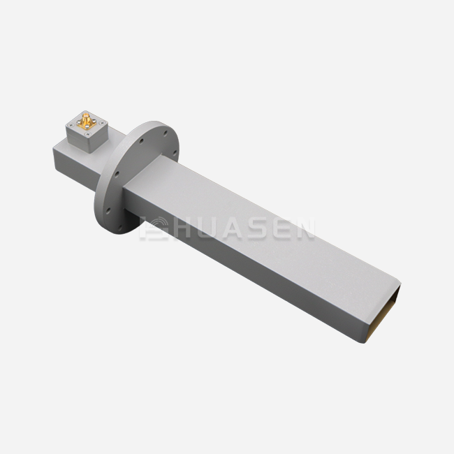
For satellite communication networks to work, the broadcast parts need to be able to keep the signal quality good over long distances and with a lot of power. Rectangular waveguide tubes work very differently from coaxial lines because they send electromagnetic energy through controlled field patterns inside their circular metal structure. This design gets rid of the dielectric losses that come with regular cables at frequencies above 1 GHz. This makes waveguide tubes essential for Ku-band (12–18 GHz), Ka-band (26.5–40 GHz), and new V-band satellite uses. Because of the way these guides are shaped, there is a cutoff frequency below which transmission can't happen. This creates a high-pass filtering effect that naturally blocks interference at lower frequencies.
Common Materials Used in Waveguide Construction
The choice of material has a big impact on both the electrical performance and the mechanical life of satellite systems. Aluminium metals are most commonly used in space-qualified and airborne uses because they have a good strength-to-weight ratio. 6061-T6 aluminium is especially popular because it is easy to machine and doesn't rust when anodised properly. Brass is a better conductor of electricity than other materials, so it lowers ohmic losses in ground-based systems where weight is not as important. Copper has the lowest resistance loss, but it needs to be protected with a covering to keep it from rusting in outdoor settings.
New technologies have made it possible to make hybrid materials that are specifically designed for certain uses. For UAV and satellite payload installations, carbon fibre-reinforced polymer waveguide tubes make a big difference in weight reduction. However, their frequency range and power handling are still restricted when compared to metal options. More and more, manufacturers are coating interior areas with electroless nickel or silver. This improves conductivity and protects base metals from external damage.
Standard Versus Custom Dimensional Requirements
Standard rectangular waveguide Tubes are named in a set way, like the WR series, where WR-90 is the name of a guide with an internal width of 0.900 inches that works best at X-band frequencies between 8 and 12 GHz. These standard measurements make it possible for parts from different makers to work together and make buying parts easier for common uses. When satellite systems need to work at non-standard frequencies, need to extend their bandwidth beyond normal ranges, or have serious space limitations that stop them from using standard flanges, they need to be made to specific measurements.
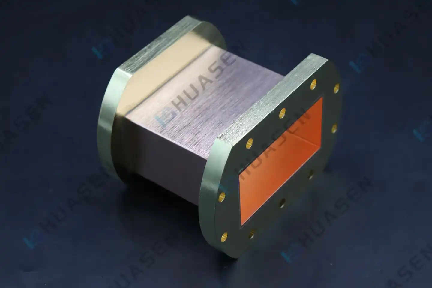
The size and shape of a waveguide tube directly affect how electromagnetic waves behave. The cutoff frequency and working bandwidth are set by the broad wall dimension (width), while the narrow wall dimension (height) affects the power handling capacity and mechanical strength. Insertion loss increases with the length of the waveguide tube runs, so accurate loss estimates are very important for system planning. We make both single-ridge and dual-ridge configurations at Huasen Microwave that change these dimensional connections. When compared to standard rectangular guides, dual-ridge designs increase the useful bandwidth by about 2:1 while dropping the cutoff frequency. This lets smaller assemblies cover a wider range of frequencies. Single-ridge versions are great when the installation room is limited because they reduce the size while keeping the performance the same.
Criteria for Choosing the Right Waveguide Tube Dimensions
Matching Dimensions to Operating Frequency Bands
There are different standard frequency ranges for satellite transmission, and each one needs waveguide tubes of the right size. Larger cross-sections, like WR-229 or WR-187, are usually used by C-band ground stations (3.7–4.2 GHz downlink, 5.925–6.425 GHz uplink), while WR-75 or WR-62 are used by Ku-band Very Small Aperture Terminals (VSATs). Even smaller guides, like WR-42 and WR-28, are being used by Ka-band high-throughput satellites. This makes manufacturing standards even more important. Operating well above the cut-off frequency—usually between 125% and 190% of cut-off—is a basic design rule that makes sure single-mode transmission and avoids multimode interference.
Dimensional Impact on Insertion Loss and VSWR
The voltage standing wave ratio is a key measure of how well the impedance matching works along the communication line. Bad control of dimensions during production creates breaks in the signal that lead to signal echoes, which raise VSWR and lower the power sent to satellite stations. For important areas at Ka-band and above, custom waveguide tubes must keep their dimensions within ±0.001 inches. Insertion loss is made up of resistive losses in the electrical walls and losses caused by any flaws in the geometry or the surface.
Because there are more currents running along the walls of a smaller waveguide tube cross-section, it naturally has higher loss per unit length. Engineers must carefully model cumulative loss when they set custom measurements for long transmission runs between the equipment rooms at the ground station and the antenna feeds. A Ka-band system with a 30-metre waveguide tube run might lose 2-3 dB more signal than one with a shorter path. To close the link budget, higher-power amps or bigger antenna openings might be needed. For all custom setups, we give you full attenuation specs across frequency bands. This lets you do accurate system-level loss budgeting before you commit to buying something.
Collaborating with Manufacturers on Custom Specifications
For custom waveguide tube procurement to go well, there needs to be a clear technical discussion and sensible expectations about when things will be done. Clients should give full details about the frequency range they need, how much power they can handle (both average and peak), the environment they will be exposed to, their preferred flange contact, and the physical limits of the enclosure. Lead times are usually 4–8 weeks longer for custom tools made for nonstandard cross-sections than for catalogue items, but this investment pays off when standard goods can't meet system requirements.
The size and shape of a waveguide tube directly affect how electromagnetic waves behave. The cutoff frequency and working bandwidth are set by the broad wall dimension (width), while the narrow wall dimension (height) affects the power handling capacity and mechanical strength. Insertion loss increases with the length of the waveguide tube runs, so accurate loss estimates are very important for system planning. We make both single-ridge and dual-ridge configurations at Huasen Microwave that change these dimensional connections. When compared to standard rectangular guides, dual-ridge designs increase the useful bandwidth by about 2:1 while dropping the cutoff frequency. This lets smaller assemblies cover a wider range of frequencies. Single-ridge versions are great when the installation room is limited because they reduce the size while keeping the performance the same.
Selecting Materials for Custom Waveguide Tubes: Pros and Cons
Metallic Materials: Aluminium and Brass Comparison
Aluminium is the most common material used in satellite transmission waveguide tubes because it is light, conducts electricity well, and doesn't rust when the surface is cleaned properly. 6061-T6 aluminium has a tensile strength of about 45,000 psi, which is strong enough for most installs on the ground and many uses in the air. Its thermal expansion coefficient needs to be thought about in systems that go through big changes in temperature because changes in size can affect how well the electricity works. Brass, which is made up of copper and zinc, is about 28% better at conducting electricity than aluminium. This means that there is less insertion loss in long transmission runs.
Weight considerations often drive material selection for mobile satellite stations and aircraft uses. Aluminium is three times lighter than brass, which has a density of 8.5 g/cm³. This is very important for installations on aeroplanes, drones, and satellites, where every gram can affect fuel economy or launch costs. Cost research has to take into account both how much the raw materials cost and how hard the work is to do. Brass is easier to work with than aluminium, which could make up for its higher cost when working with complicated shapes that have a lot of bends and changes.
Surface treatment selection influences long-term reliability regardless of base material choice. Aluminium waveguide tubes that will be installed outside are protected against rust with chromate conversion coating or type II anodising. They are then electrolessly nickel-plated on the inside to improve their transmission. Silver plating is often used to keep brass parts from rusting and to keep their great surface conductivity. In harsh marine or industrial settings, where salt spray and chemical contaminants speed up degradation, these protection layers need to be checked on a regular basis.
Alternative Materials for Specialised Applications
Non-metallic waveguide tube materials are sometimes used in advanced satellite systems when weight reduction or special electromagnetic qualities are very important. Carbon fibre composite waveguide tubes can have densities below 1.6 g/cm³ while still being structurally rigid. This makes them a good choice for high-altitude platform stations and satellite groups where the cost of the mission depends on the launch mass. Because they can only handle a small amount of power, they can only be used for getting signals or low-power transmission chains that use less than 100 watts of normal power.
Metallic and hybrid materials have very different thermal control properties. When high power is being sent, aluminium's thermal conductivity of 167 W/m ·K effectively gets rid of resistive heating. On the other hand, materials with conductivity below 1 W/m ·K may need active cooling or heat sinking for even mild power levels. Testing for environmental longevity shows that composites can handle changes in temperature and pressure well, but they need UV-resistant resin formulas to be used outside without protective radomes. Lifecycle cost analysis, which goes beyond the original procurement price, is becoming more and more important in material selection. Aluminium and brass waveguide tubes last a very long time.
Conclusion
Custom waveguide tubes are important parts of modern satellite communication systems' infrastructure. The performance and dependability of the links depend on the right choice of dimensions and material specifications. It's hard to balance electromagnetic needs with mechanical limits, the need for long-term longevity in harsh environments, and budget constraints. This is why you need experienced production partners to help with the engineering analysis. For procurement to go smoothly, technical requirements must be clearly communicated, timelines must be reasonable, and suppliers must be thoroughly screened to make sure that the parts supplied meet strict performance standards for their entire operational life.
FAQ
1. How do the choices of materials affect how well waveguides work in satellite applications?
Three main performance qualities are affected by the choice of material. Insertion loss is directly related to electrical conductivity. Copper, brass, and aluminium all have lower absorption than aluminium, but at Ku-band frequencies, the difference is usually less than 0.5 dB per metre. Because it is lighter, metal is better for projects in the air and space, even though it loses a little more. Corrosion resistance varies a lot. In marine settings, properly anodised aluminium performs better than brass unless brass is protected with the right covering. To keep mechanical stress from happening during temperature cycling, the materials used for the mounting framework must have the same thermal expansion rate as the Waveguide Tube.
2. What kind of limits do Ka-band waveguides need for their dimensions?
Ka-band devices that work above 26 GHz need tighter manufacturing tolerances than systems that work at lower frequencies. To keep VSWR standards below 1.20:1, critical measurements like internal width and height need to be controlled to within ±0.001 inches for the waveguide tube. For dependable sealing and electrical connection, the flange's flatness must not be more than a 0.0005-inch total indicator reading. Surface roughness standards get stricter, requiring 32 microinch Ra or better. This is because at these frequencies, the skin's depth concentrates current in the top layer, where flaws cause uneven loss to rise.
3. Can waveguide systems be changed or bent while they are being installed in the field?
You can't change the field around rigid rectangular waveguide tubes without changing their electromagnetic features. When something bends, dents, or changes shape, it forms impedance discontinuities that cause echoes and raise insertion loss. For complicated routeing, precision bends made in a machine to controlled shapes are needed. When an installation needs to be flexible, it needs to have flexible waveguide tube sections with a complex structure that lets them be bent within certain radius limits while still keeping electrical performance. However, these sections lose more electricity than their rigid counterparts.
Partner with Huasen Microwave for Your Custom Waveguide Solutions
As a company with 30 years of experience in specialised engineering, Huasen Microwave makes satellite transmission waveguide tubes for major phone companies, military contractors, and aircraft system designers around the world. Standard rectangular waveguide tubes come in both single-ridge and dual-ridge forms in our wide range of products. Each is designed to meet specific bandwidth and packing needs. The dual-ridge design increases the operational bandwidth while dropping the cutoff frequency. This lets smaller setups cover a wider range of frequencies. Single-ridge versions offer balanced performance in small packages, making them perfect for uses where standard rectangular guides can't be used because of size limits. We support the ability for foreign and American flange standards to be used interchangeably. This makes integration into a wide range of system designs easier.
Custom engineering services take care of special material needs, odd-shaped parts, and complicated building arrangements that can't be met by standard store items. Our quality control procedures are in line with MIL-STD and ISO standards, and every package comes with a full dimensional inspection record and electrical performance testing. As a reliable manufacturer of Waveguide Tubes that have been used in demanding satellite communication applications, we invite you to talk to our applications engineering team at sales@huasenmicrowave.com about your specific project needs and get detailed technical advice and competitive quotes.
References
1. Pozar, David M. "Microwave Engineering, 4th Edition." John Wiley & Sons, 2011.
2. Saad, Theodore S. "Microwave Engineers' Handbook, Volume 1." Artech House Publishers, 1971.
3. Balanis, Constantine A. "Advanced Engineering Electromagnetics, 2nd Edition." John Wiley & Sons, 2012.
4. IEEE Standard 148-2017. "IEEE Recommended Practice for Waveguide and Waveguide Component Measurement." Institute of Electrical and Electronics Engineers, 2017.
5. Skolnik, Merrill I. "Radar Handbook, 3rd Edition." McGraw-Hill Education, 2008.
6. Morgan, Samuel P. "Waveguide Handbook." Institution of Engineering and Technology, 1951 (Reprinted 1993).
Send Inquiry