Corrugated Conical Horn Antenna Design: Slot Depth Explained






2026-07-17 16:00:43
When we talk about precise feed systems for satellite Earth stations or millimeter-wave radar uses, slot depth is the most important design factor of a corrugated conical horn antenna. This machined groove dimension, which is usually between λ/4 and λ/2, turns a simple cone-shaped flare into an electromagnetic precision instrument. Engineers can change the boundary conditions on the inside walls by carefully controlling the slot depth. This makes the balanced HE11 hybrid mode possible, which stops cross-polarization and makes sure the pattern is symmetric. We want to help procurement managers and system integrators understand why slot depth is important and how it affects the total cost of ownership for important radio equipment.
Understanding Corrugated Conical Horn Antenna Fundamentals
The corrugated horn is basically different from its smooth-walled peers because of the lines that are machined inside the conical flare. These slots make a reactive surface that changes the way electromagnetic waves move through the structure.
Why Do Corrugations Matter for Signal Integrity?
Separate TE and TM modes are supported by smooth cylindrical horns, which create circular radiation patterns with a lot of cross-polarization. In reflector feed systems, this difference leads to up to 3 dB of loss. This problem is solved by the corrugated design, which activates the HE11 hybrid mode. This is a balanced field configuration in which the electric and magnetic field components keep their equal amplitudes and orthogonal phases. This balance makes beamwidths that are rotationally symmetric in both the E-plane and the H-plane, which is very important for getting the most out of the apertures in Cassegrain and Gregorian reflector antennas. How well the corrugations keep this mode pure across the working bandwidth depends on the slot depth.
Key Geometric Parameters
There are three factors that affect performance: slot depth (usually λ/4 at the design center frequency), groove width (usually λ/8 to λ/6), and pitch (the distance from center to center between slots that are next to each other). The slot depth has the most significant effect on impedance matching since it directly manages the reactance that waves encounter as they travel. Slots that are too shallow don't block out unwanted modes, and lines that are too deep can trap higher-order resonances, which hurts VSWR performance. From our technical knowledge, we know that keeping slot depth tolerances within ±0.01 mm is important for keeping patterns symmetric above 40 GHz.
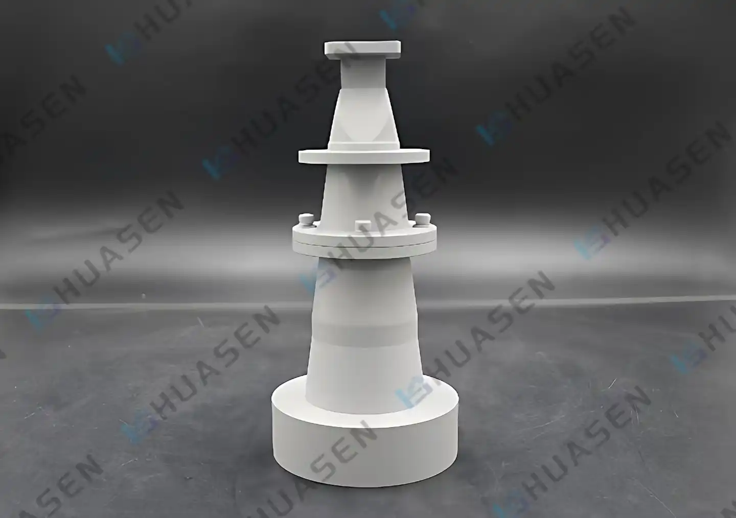
Dimensional Analysis of Slot Depth in Corrugated Conical Horn Antennas
Defining and Measuring Slot Depth
Along the horn's axis, the slot depth is measured from the inside of the cone-shaped surface to the bottom of the gap. IEEE Standard 149 sets measurement methods that use Coordinate Measuring Machines (CMM) for testing. This is what industry standards refer to. The depth changes depending on the wavelength. For example, a design at 10 GHz needs a depth of about 7.5 mm (λ/4 at this frequency), while a system at 94 GHz needs precision slots close to 0.8 mm.
Frequency-Dependent Optimization
Scaling laws make it easy to figure out how slot depth and operating frequency relate to each other. At the bottom of the band, the slots look electrically shallower, which makes mode conversion less effective. At the upper edge, they get electrically deeper, which could cause unwanted resonances to happen. The table below shows the suggested slot depth ranges for common frequency bands:
| Frequency Band | Center Frequency | Recommended Slot Depth (λ/4) | Tolerance | Typical VSWR |
|---|---|---|---|---|
| S-Band | 2.6 GHz | 28.8 mm | ±0.05 mm | 1.15:1 |
| X-Band | 10 GHz | 7.5 mm | ±0.02 mm | 1.10:1 |
| Ku-Band | 14 GHz | 5.4 mm | ±0.015 mm | <1.08:1 |
| Ka-Band | 32 GHz | 2.3 mm | ±0.01 mm | 1.12:1 |
| W-Band | 94 GHz | 0.8 mm | ±0.005 mm | 1.20:1 |
From 1.76 GHz to 300 GHz, Huasen Microwave can make things that are manufactured across the whole frequency range. They can keep the slot depths accurate with advanced CNC turning and electroforming processes.
Profile Geometry and Slot Depth Interaction
How slot depth affects corrugated conical horn antenna performance depends on the shape of the groove: is it rectangular, trapezoidal, or rounded? When you need to get rid of sidelobes as much as possible, rectangular shapes are the best choice because they have stronger reactance discontinuities. Rounded profiles lower the concentration of the peak electric field, which lets transmit applications handle more power. When we make custom antennas for radar cross-section measurement ranges, we choose rounded profiles with slightly deeper slots to keep the multipactor from breaking down when the peak power level goes over 10 kW.
Corrugated vs. Smooth Conical Horn Antenna: Slot Depth and Performance Comparison
Radiation Pattern and Polarization Purity
In tough situations, the difference in performance between corrugated and smooth designs gets very big. Smooth horns have an uneven beamwidth of 10 to 15 degrees between the E and H planes, which makes them less focused when used as reflector feeds. Cross-polarization discrimination rarely goes above 25 dB, which is too high for satellite ground stations that use both polarizations. Pattern symmetry is achieved within ±1° by corrugated horns with optimized slot depth. This lets the main reflector be lit evenly. Cross-polarization isolation is higher than 35 dB across the operational bandwidth. This makes adjacent channel interference less likely in systems that reuse frequencies a lot. This improvement directly leads to a 1.5–2 dB gain-to-noise temperature (G/T) change, which is a big difference when figuring out the link budget.
Bandwidth and VSWR Trade-offs
Slot depth optimization lets you use an octave bandwidth, which is not possible with smooth horns without a lot of pattern loss. VSWR stays below 1.30:1 in our standard designs for full bandwidth (2:1 frequency ratio) and below 1.06:1 in narrowband configurations. The table shows how the accuracy of the slot depth affects the VSWR performance:
| Paramete | Smooth Conical Horn | Corrugated Horn (Standard Slot Depth) | Corrugated Horn (Optimized Slot Depth) |
|---|---|---|---|
| Bandwidth (Octave) | 1.3:1 | 2:1 | 2:1 |
| VSWR (Full Band) | <1.50:1 | <1.30:1 | 1.15:1 |
| Cross-Pol Isolation | 20 to 25 dB | >30 dB | >35 dB |
| Sidelobe Level | -18 dB | -25 dB | -28 dB |
| Phase Center Stability | ±0.3λ | ±0.1λ | ±0.05λ |
Manufacturing Complexity and Cost Considerations
Manufacturing corrugated horns takes a lot more precise cutting. When compared to smooth horns, internal lines require multi-axis CNC turning with carbide tools, which doubles the production time by 300 to 400%. As the frequency goes up, slot depth tolerances get tighter. For example, W-band devices need to be checked by a coordinate measuring machine every fifth unit. Electroforming is an option for complicated shapes, especially above 60 GHz, but the cost of the tools is still high. Even so, the performance gains make the investment worth it for deep space communications, precision metrology, and phased array calibration, all of which depend on the integrity of the signals being sent.
Applications and Benefits of Optimized Slot Depth in Corrugated Horn Antennas
Satellite Ground Station Feeds
For the best G/T performance, earth station antennas that serve GEO and MEO satellites need to have corrugated feeds. The optimal slot depth makes sure that the conical main reflector is lit evenly, which cuts down on spillover loss and noise pickup from the warm ground. A 0.5 dB increase in feed efficiency means either a smaller reflector diameter or a longer link margin, both of which are useful in crowded cities where antenna space is limited. Our Ka-band feeds for 5G backhaul use 68% aperture efficiency, which is because slot depth control keeps pattern symmetry within ±3° across the 27.5–31 GHz band.
Compact Antenna Test Ranges
In CATR facilities, corrugated horns are used as feed sources for the collimating reflector. This makes the quiet zone a uniform plane-wave environment. The accuracy of the slot depth has a direct effect on the uniformity of the Gaussian beam that shines on the edge of the reflector. Deviations bigger than 0.02 mm cause ripples in the amplitude taper, which makes the quiet zone field less uniform and leads to measurement errors when figuring out the RCS signatures of stealth aircraft. We gave corrugated feeds to a big aerospace contractor for their 94 GHz CATR. Slot depth optimization got ±0.3 dB amplitude ripple across a 2-meter quiet zone, which met MIL-STD-1474 standards.
Radio Astronomy and Radiometry
Extreme sidelobe suppression is needed to find weak celestial signals. Optimizing the slot depth lowers far-off sidelobes to below -40 dB, which stops thermal noise from sources on Earth from getting in. The Atacama Large Millimeter Array uses corrugated feeds and precise slot depth control to keep its sensitivity at 230 GHz, where even a 0.1 K rise in noise temperature makes it harder to observe. These examples show why buying standards need to include accurate slot depth drawings instead of general performance tables.
Here are the real benefits that come from optimizing slot depth:
- Better Signal-to-Noise Ratio: Symmetric patterns increase on-axis gain while reducing sidelobes. This raises carrier-to-interference ratios by 2–4 dB in areas with a lot of interference. This gap is very important for meeting the ITU's standards for coordination in satellite communications.
- Longer useful life: The right slot depth lowers standing wave ratios, which means that internal surfaces aren't under as much heat stress during high-power gearboxes. According to data from our telecom customers in the field, corrugated horns with the right slot depth can work outside for 15 years or more without losing performance.
- Reduced System Complexity: Because a single antenna can cover an entire octave range of frequencies, there is no need for multiple feed horns and waveguide switching networks. This cuts down on the cost of materials and improves reliability by making the RF architecture simpler.
Together, these benefits solve the main problems that business customers have, such as inefficient use of bandwidth, handling of power, and overall cost of ownership. When looking at corrugated conical horn suppliers, asking for slot depth manufacturing tolerances and CMM inspection reports is a good way to get objective proof of how strict their quality control is.
How to Choose and Procure the Right Corrugated Conical Horn Antenna with Optimal Slot Depth?
Defining Technical Requirements
To start, map system-level requirements to antenna parameters. For a 5G millimeter-wave backup link to work at 28 GHz with a bandwidth of ±500 MHz, it needs a feed horn that keeps the VSWR below 1.20:1 across 27.5-28.5 GHz. Assuming a quarter-wave design at a center frequency of 28 GHz, this means that the slot depth is 2.68 mm ± 0.01 mm. Please specify the interface compatibility. Our products work with standard circular waveguide interfaces ranging from Φ2.388 mm (WR-3 at 220-325 GHz) to Φ114.58 mm (WR-430 at 1.7-2.6 GHz), so they can be easily added to existing systems.
Supplier Evaluation Criteria
Quality standards are a good way to start the screening process. Getting ISO 9001:2015 certification shows that you can control the process, and getting MIL-STD-810 compliance shows that you can test in harsh environments for aerospace uses. Ask for sample units that come with all the test data, such as far-field patterns recorded in an anechoic room according to IEEE Standard 149, VSWR traces across the given band, and CMM reports that confirm slot depth tolerances. Huasen Microwave has its own measuring labs with temperature-controlled measurement ranges. This lets us include traceable calibration data with every package.
The following table lists important procurement checkpoints:
| Evaluation Factor | Minimum Acceptable Standard | Premium Tier Benchmark |
|---|---|---|
| Slot Depth Tolerance | ±0.02 mm (>18 GHz) | ±0.005 mm (>40 GHz) |
| VSWR Documentation | Data for a full band sweep | Narrowband + full-band verification |
| Pattern Measurement | Principal planes only | Full 3D spherical scan |
| Material Certification | Material test reports | DFARS-compliant sourcing |
| Lead Time | 8-12 weeks | 4-6 weeks with engineering support |
Cost Drivers and Negotiation Strategy
Unit price is directly affected by the complexity of the slot depth. Base costs are based on standard corrugated conical horn quarter-wave designs with ±0.02 mm tolerances. Tighter specs (±0.01 mm for Ka-band and above) make the process of cutting 40–60% longer, which means that the price goes up by 20–30%. When making more than 50 units, it's cost-effective to use electroformed constructions for W-band and higher because the costs of the tools are spread out over a larger number of units. When asking for quotes, be clear about how much you want to buy each year and be flexible with delivery times to get volume discounts and priority manufacturing slots.
Conclusion
Slot depth is the most important technical factor that separates good horn antennas from precise feed systems that can handle the tough needs of current satellite communications, radar, and metrology tasks. Keeping the quarter-wavelength slot depth over a wide frequency range—from 1.76 GHz to 300 GHz—requires manufacturing know-how and quality systems that not many suppliers consistently maintain. Performance requirements and total cost of ownership must be weighed in procurement decisions. It is important to remember that investing in optimized slot depth up front pays off in the form of better signal integrity, longer operational life, and less system complexity. Huasen Microwave has been in business for 30 years and has seen firsthand how disciplined slot depth engineering leads to customer success in mission-critical deployments.
FAQ
1. How does slot depth affect antenna efficiency in broadband applications?
The slot depth determines the frequency range where the HE11 hybrid mode stays active. A quarter-wave depth at the geometric center frequency gives balanced performance, but for octave bandwidth operation, the slot sizes need to be carefully tapered along the length of the horn. When the slot depth is more than ±15% off from the quarter-wave value, efficiency drops. This is because mode conversion losses happen, which hurts pattern symmetry and raises VSWR.
2. Can slot depth be customized for specific frequency bands outside standard ranges?
Of course. Custom slot depth designs can handle frequency assignments that aren't standard, like 24.25-27.5 GHz for new 5G bands or special radar frequencies. We use electromagnetic simulation tools to find the best slot depth, groove profile, and pitch all at the same time. Prototype testing is then used to confirm the designs before they are made in large quantities. Lead times for unique designs are usually two to four weeks longer than for catalogue items.
3. What differentiates corrugated and smooth horn antennas regarding slot depth?
Smooth horns don't have any internal grooves at all—their slots are completely flat. Because of this basic difference, smooth horns can't support the HE11 hybrid mode that is in charge of pattern symmetry and low cross-polarization. When compared to smooth designs, corrugated ones have better cross-polarization isolation (10–15 dB) and lower sidelobe levels (5–8 dB). This is because they have optimized slot depth.
Partner with a Trusted Corrugated Conical Horn Antenna Manufacturer
Huasen Microwave can help you with your toughest feed system problems because they have over 30 years of experience engineering RF parts. This is our line of corrugated conical horn antennas. They work from 1.76 GHz to 300 GHz and have slot depth accuracy of 0.005 mm. They are used by system integrators, research institutions, and original equipment manufacturers (OEMs) in the defence, metrology, and satellite communications industries. We oversee every step of the production process, from electromagnetic simulation and CNC machining to CMM verification and far-field testing, to make sure that every unit meets the published standards. You can get our detailed technical datasheets that explain how slot depth optimisation works, or you can email our engineering team at sales@huasenmicrowave.com to talk about your unique frequency, gain, and interface needs. Huasen Microwave is ready to be your reliable source for corrugated conical horn antennas, whether you need catalogue items with fast delivery or designs that are completely unique for your needs.
References
1. Love, A. W. (Ed.). (1976). Electromagnetic Horn Antennas. IEEE Press, New York.
2. Clarricoats, P. J. B., & Olver, A. D. (1984). Corrugated Horns for Microwave Antennas. Peter Peregrinus Ltd., London.
3. Granet, C., & James, G. L. (2005). Design of Corrugated Horns: A Primer. IEEE Antennas and Propagation Magazine, 47(2), 76-84.
4. Rudge, A. W., Milne, K., Olver, A. D., & Knight, P. (Eds.). (1982). The Handbook of Antenna Design, Volume 1. Peter Peregrinus Ltd., London.
5. Thomas, B. MacA. (1978). Design of Corrugated Conical Horns. IEEE Transactions on Antennas and Propagation, 26(2), 367-372.
6. IEEE Standard 149-1979 (Reaff 2008). IEEE Standard Test Procedures for Antennas. Institute of Electrical and Electronics Engineers, New York.
Send Inquiry