Compact Device Integration Using Planar Slot Antenna Structures






2026-07-12 22:36:00
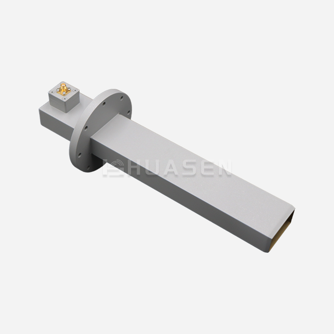
Putting together small devices requires antenna systems that have a small size but strong RF performance. This problem can be solved by planar slot antenna designs, which allow for flush-mount placement without affecting the signal integrity. These waveguide-fed radiating elements are great at controlling the direction of radiation and handling power. This makes them perfect for 5G base stations, aircraft telemetry, and marine navigation systems that need to save room without sacrificing reliability. Their low-profile design gets rid of air drag and makes it easier to put together mechanical parts for telecommunications infrastructure.
Understanding Planar Slot Antenna Fundamentals
Electromagnetic Principles Behind Slot Radiation
Aperture theory says that electromagnetic energy can leave a conductive surface through carefully cut holes. This is how planar slot antennas work. In contrast to normal wire elements, these structures radiate as magnetic dipoles, and the field distribution is controlled by the size of the slots and the waveguide activation modes. Babinet's concept is used by the radiation mechanism to make predictable beam patterns that can be used for directional communication lines. Because of this basic behavior, designers can control polarization and beamwidth by making simple geometric changes instead of using complicated feed networks. This makes the system simpler.
Performance Metrics That Matter for Integration
Bandwidth properties have a direct effect on multi-band compatibility. Huasen Microwave's waveguide slot array technology gets 5-8% immediate bandwidth across the 1-40 GHz spectrum. This means that a single antenna can cover a wide range of frequencies. Return loss performance below -15 dB makes sure that power is transferred efficiently with little bounce, which protects transceivers that are sensitive in radar systems and base station front ends. The vertical beamwidth of 3.2 to 4.5 degrees allows precise control of elevation for sectored coverage in cellular networks, which keeps nearby cells from interfering with each other.
Structural Advantages for Space-Constrained Applications
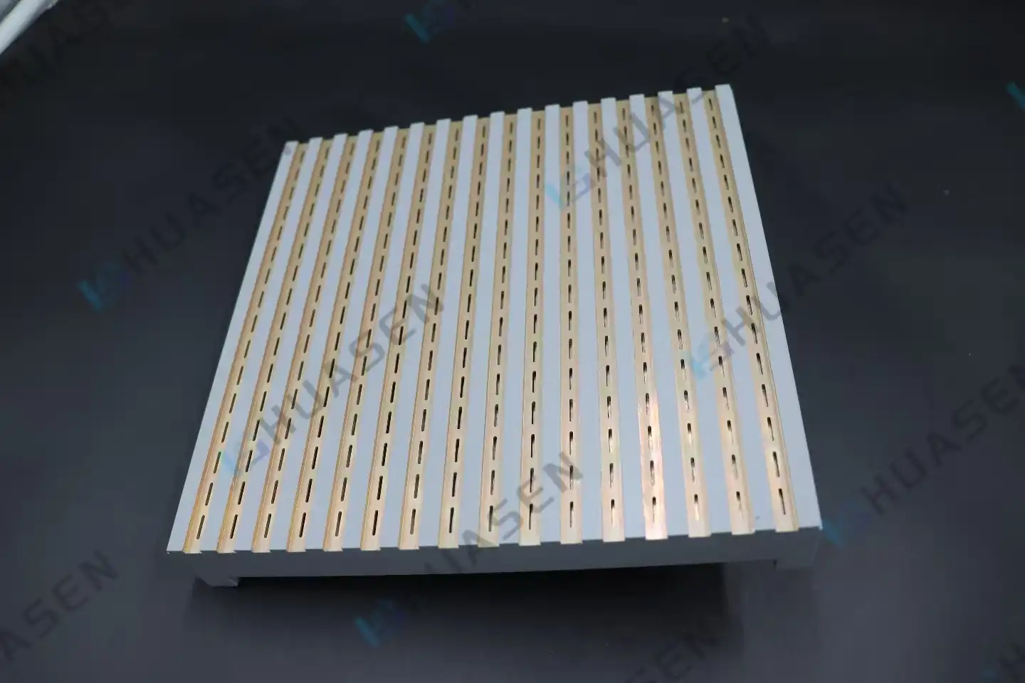
The small waveguide slot array design gets rid of any protrusions on the outside, which lets it be mounted flush on the fuselages of airplanes and spaceships. This flush connection keeps the structure strong in places with a lot of shaking, like on ships and robotic aerial systems. In aircraft uses, lightweight construction lowers payload costs while still meeting the MIL-STD-810 requirements for mechanical robustness. The omnidirectional horizontal pattern that goes all the way around 360 degrees gets rid of blind spots in surveillance radars and transmission relays that don't use moving parts.
Comparative Analysis: Why Choose Slot Structures Over Alternatives?
Performance Benchmarking Against Microstrip and Patch Designs
At millimeter-wave frequencies, where substrate tangent delta matters, microstrip patch antennas lose more than 2 dB of their dielectric strength. Using air-filled waveguides in planar slot antenna setups keeps efficiency above 85% even at Ka-band, which makes them better for high-power radar emitters. For bandwidth growth, patch elements need thick supports, which makes them heavier and makes it harder to control the temperature. In pulsed radar uses, waveguide slots can easily handle peak powers of more than 10 kW, but printed circuits can burn out at 100W of constant operation.
Form Factor Comparison with Traditional Dipole and Yagi Arrays
When dipole arrays stick out from mounting surfaces, they create drag factors that make airplanes use 3–5% more fuel on external pods. Yagi-Uda designs need long boom frames that can't be used on small UAV platforms with a width limit of 200 mm. Slot array openings (planar slot antennas) are built right into equipment enclosures and can be used as both radiation elements and pressure bulkheads in airplane systems that are under pressure. Compared to multi-element wire antenna systems that need separate frames and radomes, this structure's efficiency cuts down on the number of parts needed and the time it takes to put them together.
Cost-Effectiveness Versus Emerging Fractal Geometries
Fractal antenna designs offer wideband operation, but they need 50-micron trace tolerances on multi-layer PCB manufacturing, which makes each unit 40% more expensive than with a normal plan. When feature sizes get close to the limits of photolithography, performance changes from batch to batch, which makes manufacturing less repeatable. CNC cutting with 25-micron accuracy is used to make waveguide slot arrays, which makes sure that the electrical properties stay the same from one production run to the next. When more than 500 units are shipped each year, tooling amortization favors slot structures. This is in line with base station deployment scales, where procurement managers put supply chain security over experimental designs.
Integrating Slot Antennas into Compact Devices: Design and Simulation
Geometry Optimization for Multi-Band Coverage
Through half-wavelength connections, slot length determines resonance frequency. Typical slot lengths range from 3.75 mm at 40 GHz to 75 mm at 2 GHz. Adjustable planar slot antenna plans let you change the frequency without having to remake the waveguide housing. This speeds up the development process for custom base station antennas. In phased array designs, offset placement controls coupling coefficients, which lets amplitude tapering happen to get rid of sidelobes below -25 dB. This geometric freedom makes fast prototyping possible for specific uses, such as electronic countermeasure systems that need nulling patterns that can change.
Material Selection and PCB Integration Strategies
Aluminum metal housings have a yield strength of 55 MPa and a conductivity of 37 million S/m, so they lose very little ohms. MIL-STD-810 Method 509 says that gold plating on the sides of slots keeps them from rusting in marine settings where they are exposed to salt spray. Hybrid designs are possible with substrate-integrated waveguide transitions that let slot arrays join to planar RF circuits. This makes it easier to integrate MMIC amplifiers and digital beamformers. Rogers RO4003C laminates support co-design methods because they have low-loss transmission (tan = 0.0027) and are mechanically stable from -55°C to +125°C.
Simulation Workflow Using Advanced EM Tools
HFSS finite element analysis checks that the impedance matching is correct across the operational band and finds resonant mode changes that are caused by manufacturing errors. Time-domain solvers in CST Microwave Studio can predict transient reactions that are important for pulse radar uses with rise times of less than one nanosecond. Parameter sweeps show how sensitive the system is to changes in slot width, which helps CNC machine vendors set tolerances. By using near-field probing in virtual anechoic rooms to get radiation efficiency metrics, it is possible to match generated gain patterns with measured data to within 0.3 dB, which speeds up certification testing.
Procurement Considerations for Slot Array Antennas
Evaluating Supplier Capabilities and Certifications
Quality approvals show that the production process is mature. Following ISO 9001:2015 standards ensures that process controls are written down, which lowers failure rates to less than 200 parts per million for large orders. RoHS approval proves that lead-free soldering can be used with automatic SMT lines to make base stations. Suppliers who offer MIL-STD-461 EMI tests show they are ready for defense contracts, where radiated emissions below 80 dBµV/m keep nearby electronics from interfering. Ask for sample inspection records that show readings of return loss at different temperatures to make sure that the performance of the planar slot antenna stays stable when temperatures change from -40°C to +85°C.
Customization Flexibility Versus Off-Shelf Solutions
Standard catalogue Slot Antenna items work well for testing, but they don't always meet the impedance needs of the end system. Custom slot spacing meets specific beamwidth goals for sectored cellular coverage. In urban valleys, 65-degree angle patterns provide the best capacity. Customizing the polarization makes MIMO deployments possible, and spots that are not parallel to each other allow for spatial sharing. Customized designs take between 6 and 10 weeks to make, so you need to get involved early in the system planning stages. Off-the-shelf versions can be sent out within 48 hours, but they only come in standard ISM bands, which means they can't be used in licensed spectrum areas.
Volume Pricing and Supply Chain Resilience
When you buy more than 1,000 pieces, the unit cost goes down by 30%, which is good for equipment makers who are putting in place 5G infrastructure across the country. Talk about framework deals that include yearly volume promises. This will protect prices from changes in raw materials. Dual-source methods lower geopolitical risks, especially for aerospace projects with delivery plans that last more than one year. Check inventory backups for long-lead parts like precision waveguide flanges to make sure production doesn't stop when chip shortages affect active phased array modules.
Future Outlook and Innovations in Slot Array Technology
Miniaturization Trends for mmWave and Beyond
New 6G frequency allocations above 100 GHz need slot lengths below 1.5 mm, which is close to the limits of what can be machined normally. Photolithographic printing on silicon surfaces makes it possible to make planar slot antennas with features as small as 500 microns, which can be directly integrated with CMOS beamforming ICs. By getting rid of wire bonds and transmission line changes, these monolithic apertures lower insertion loss, which is important for keeping 20 dB noise figures in satellite ground connections. By printing dielectric-filled lattice structures in three dimensions, gradient-index lenses are made around slot arrays. These lenses improve directivity by 6 dB without making the opening size bigger.
Multi-Band Improvements Made Possible by Adjustable Apertures
Dynamic slot activation is made possible by MEMS switches built into waveguide walls. This changes the operating bands from C-band to X-band in 10 microseconds. Liquid crystal substrates let you change the permittivity based on voltage, which changes the resonant frequencies by about 8% for flexible spectrum management. These designs can be changed to support cognitive radio applications where base stations avoid interference on their own, which makes use of the spectrum more efficiently in crowded cities. With a single-feed excitation, prototype tests show that stacked slot shapes can cover 24–40 GHz and achieve a 40% instantaneous bandwidth.
Improvements in MIMO Integration and Beamforming
Massive MIMO systems need 64–256 element groups with spacing that is less than a wavelength, which makes it hard to control the heat in high-power emitters. Through natural convection, slot antenna slot array designs get 200W/element power density by spreading heat across waveguide housings. Putting digital beamforming ASICs next to slot lines cuts cable losses by 3 dB, which makes the power that is sent out by satellite communication nodes more even. In real time, machine learning techniques improve excitation coefficients by 35 dB, blocking disturbance sources and keeping the main beam's accuracy within 0.5 degrees.
Conclusion
Planar slot antenna designs offer the best combination of small size and high RF performance for uses that require integrated devices. Their ability to be flush-mounted, to cover all directions, and to provide precise beamwidth control meet important needs in radar systems, flight platforms, and telecommunications infrastructure. The waveguide-fed system can handle a lot of power while keeping efficiency above 85%, which makes it better than microstrip options in tough conditions. As wireless networks move toward millimeter-wave bands and huge MIMO designs, slot array technology keeps getting better with features like reconfigurable apertures and merging into a single piece. Strategic buying from approved sources protects the supply chain for large-scale operations.
FAQ
1. What bandwidth can slot arrays realistically achieve?
Normal resonant spots give off 5–8% of the bandwidth, which is enough for narrowband radar and point-to-point lines. This can be raised to 20 to 25 percent with advanced designs that use stacked cavities or metamaterial loading. This allows for broad messaging across multiple 5G NR bands. The trade-off is a higher appearance and a more complicated planar slot antenna design, which needs to be carefully compared to the system requirements.
2. How do environmental factors affect slot antenna performance?
The waveguide channel becomes less tuned when moisture gets in, which changes the resonant frequencies. Using PTFE or plastic for radar shielding keeps the electrical clearness while stopping humidity. Aluminum housings expand and contract when the temperature changes, so designs that work in temperatures from -40°C to +85°C need to include mechanical stress release. MIL-STD-810 Method 509 says that all RF surfaces must be gold or nickel-plated before they can be exposed to salt fog.
3. Can slot arrays support circular polarization?
Crossed-slot arrangements with phase changes of 90 degrees create circular polarization that is good for satellite ports. An axial ratio below 3 dB across scan angles of ±30 degrees needs very accurate cutting with errors less than 50 microns. On the other hand, rotating four linearly polarized holes one after the other produces wideband circular polarization with loose construction tolerances, which is better for mass production.
Partner with Huasen Microwave for Advanced Slot Array Solutions
Huasen Microwave designs Planar Slot Antenna systems that are made to fit your specific connectivity needs. Our waveguide slot array designs offer coverage in all directions from 3.2 to 4.5 degrees vertically, and can handle difficult tasks from 1 to 40 GHz. We offer full customisation of slot shape, polarisation, and power handling specs. We have 30 years of experience in RF technology and are ISO 9001:2015 certified. Our expert team can help with simulations, validate test data, and meet flexible delivery dates, whether you need prototypes for testing 5G infrastructure or large quantities for aerospace projects. Talk to a reputable manufacturer to speed up the development of your next-generation wireless platform. Get in touch with our tech team at sales@huasenmicrowave.com to talk about your bandwidth needs. Within 48 hours, you'll get full performance simulations.
References
1. Balanis, Constantine A. (2016). Antenna Theory: Analysis and Design, 4th Edition. Wiley-Interscience, Hoboken, New Jersey.
2. Elliott, Robert S. (2003). Antenna Theory and Design, Revised Edition. IEEE Press, Piscataway, New Jersey.
3. Pozar, David M. (2012). Microwave Engineering, 4th Edition. John Wiley & Sons, Hoboken, New Jersey.
4. Mailloux, Robert J. (2017). Phased Array Antenna Handbook, 3rd Edition. Artech House, Boston, Massachusetts.
5. Volakis, John L. (2007). Antenna Engineering Handbook, 4th Edition. McGraw-Hill Professional, New York, New York.
6. Hansen, Robert C. (2009). Phased Array Antennas, 2nd Edition. John Wiley & Sons, Hoboken, New Jersey.
Send Inquiry