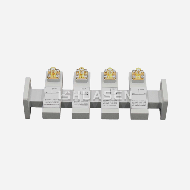
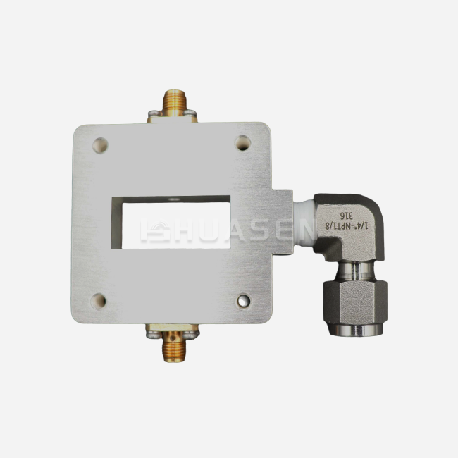
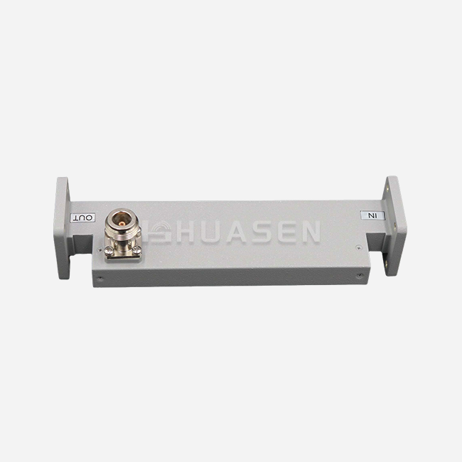
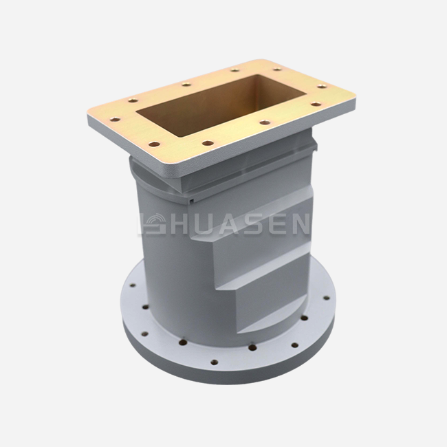
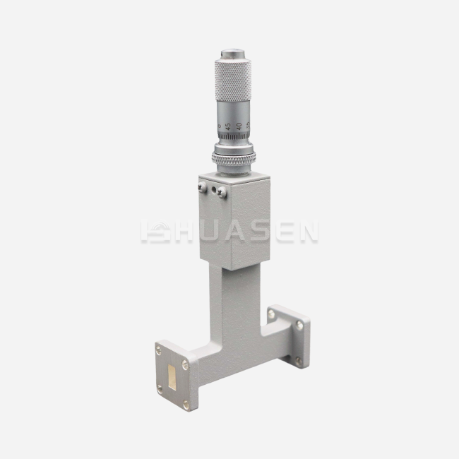
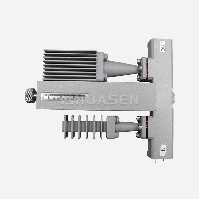
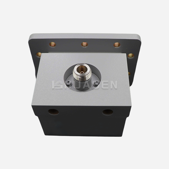
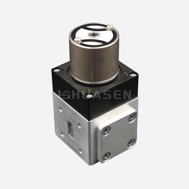
Coaxial Load Applications in Radar and Antenna Test Systems






2026-07-20 16:01:33
A coaxial load is an important part of radar and antenna test systems because it absorbs RF energy to keep signals from reflecting and to protect measurement equipment. By giving stable impedance matching over a wide frequency range, from DC to 60GHz, these precision devices make sure that accurate system characterisation is possible. Coaxial loads protect measurements and equipment in modern test facilities, whether they are testing a vector network analyser or making sure that high-power radar emitters work properly.
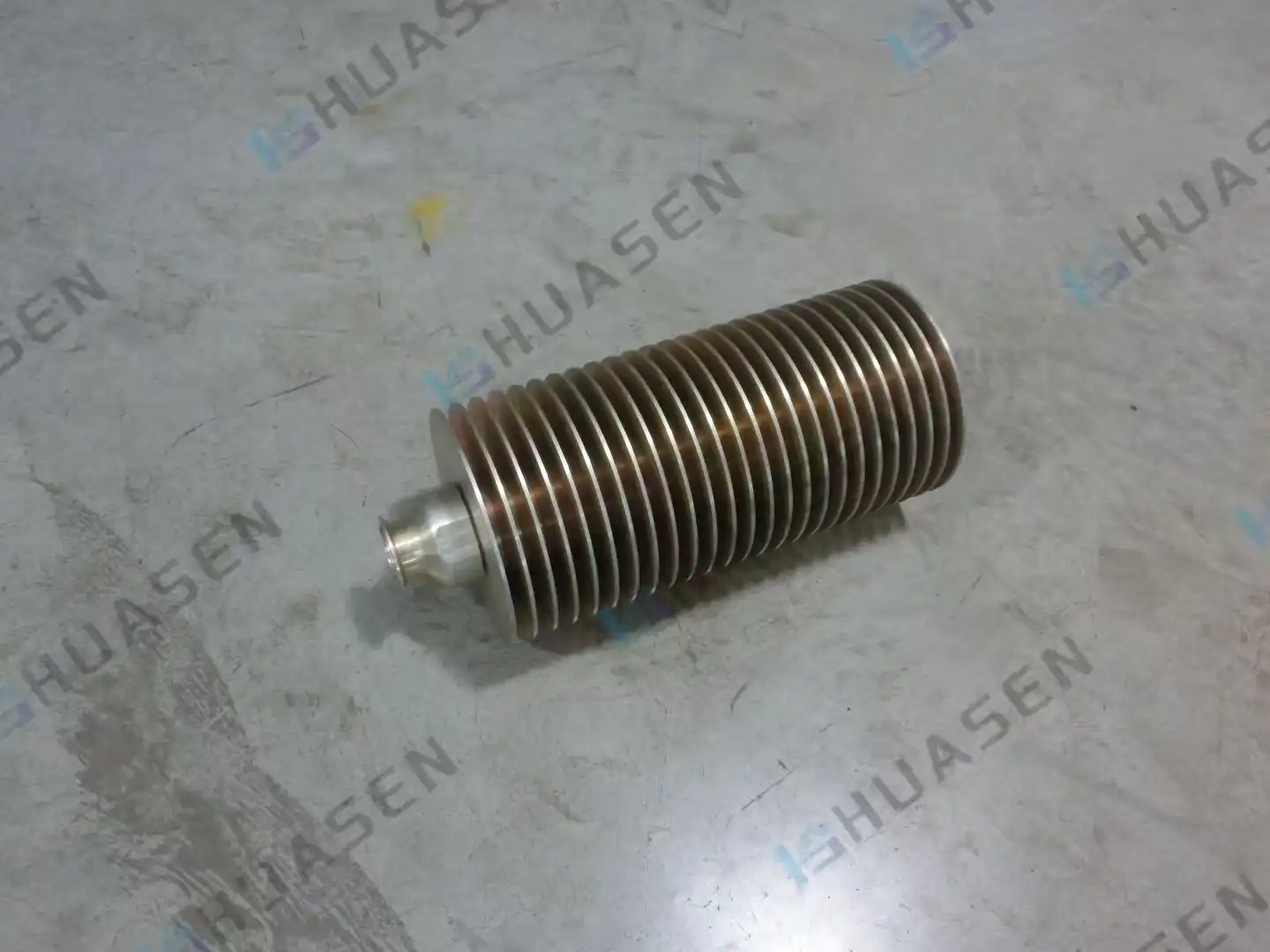
Understanding Coaxial Loads in Radar and Antenna Testing
What Defines a Coaxial Load in RF Testing?
A coaxial load is a passive RF termination that is meant to take in electromagnetic energy without sending it back into the system. Instead of attenuators, which lower the signal power while passing it through, or fake loads, which are mostly used for testing transmitters, coaxial loads end transmission lines with matching impedance (usually 50 ohms) to get rid of standing waves that mess up readings. This difference is important when choosing parts for precise test settings where even small echoes can hurt the quality of the data.
Core Types and Their Functional Differences
There are three main types of coaxial load setups that test engineers see. Matched loads have the same resistance across their entire working span. This means they can be used as measuring standards or as general-purpose terminations. Different impedances are purposely introduced by unmatched loads for specific testing cases. Even though they're not technically absorptive loads, open- and short-circuit terminals are used as standards when calibrating a vector network analyser. Each type meets different measurement needs in radar characterisation and antenna pattern analysis.
Working Principles Behind Different Load Technologies
Three different ways of absorbing energy are used by modern coaxial loads. Precision thin-film or thick-film resistors are housed in small housings in resistive loads, which give great performance from DC to high frequencies with little low-frequency feedback. Absorptive loads use microwave-absorbing dielectrics that work best at millimetre-wave frequencies, which are higher than the range where resistive elements don't work as well. High-power versions use plate-type ceramic substrates or liquid cooling systems to constantly get rid of hundreds of watts of heat. When buying, teams understand these rules, they can better match load technology to application needs.
Decoding Critical Datasheet Parameters
When looking at coaxial loads, four specs help people decide what to buy. The frequency range tells you the operational bandwidth. For example, a DC-to-18GHz load covers most commercial radar bands, and a 60GHz capability can handle new millimetre-wave systems. VSWR, or Voltage Standing Wave Ratio, measures how much power is reflected. High-end units get VSWR values below 1.03, which means that less than 0.7% of the power that comes in is reflected back. Power dealing is broken down into average (continuous) and peak rates. If you mix up these numbers, your device could fail due to heat. Mechanical coupling is ensured by connector compatibility. Test instruments mostly use N-type, SMA, and 2.92mm interfaces.
Table 1: Key Coaxial Load Specifications for Test System Selection
| Parameter | Standard Performance | High-Performance | Application Impact |
|---|---|---|---|
| VSWR | ≤1.20:1 | ≤1.03:1 | Lower values reduce measurement uncertainty in antenna patterns |
| Frequency Range | DC–18 GHz | DC–60 GHz | Extended range supports multi-band radar and satellite communication testing |
| Average Power | ≤50 W | ≤400 W | Higher ratings enable full-power transmitter characterization without external cooling |
| Peak Power | ≤500 W | ≤5000 W | Critical for pulsed radar systems where instantaneous power exceeds average by 10x |
Core Applications of Coaxial Loads in Radar and Antenna Test Systems
Radar Transmitter Calibration and Power Verification
Coaxial loads are used instead of antennas during radar system commissioning so that full-power testing can happen without sending out signals. This application is very useful for describing high-power radar transmitters that send out kilowatts of pulsed RF energy. The load has to be able to handle high power while staying stable in terms of temperature over long test runs. Long-term operation is possible with oil-cooled or forced-air loads, which let engineers check the output power, spectral purity, and pulse features against the design requirements. Without enough load capacity, test facilities can't make sure that radars work safely before they are sent out into the field.
Antenna Pattern Measurement and Range Calibration
Precision coaxial loads are used to close off test tools' and reference antennas' empty ports in anechoic rooms and outdoor antenna ranges. When measuring radiation patterns, any reflection from instruments or cables that aren't properly terminated shows up as a measurement error. These unwanted signals can't get through ultra-low VSWR loads (≤1.05:1), which lets you get a good picture of the antenna's gain, sidelobe levels, and polarization purity. When premium loads are used, the data quality directly affects whether antenna designs meet requirements. This is especially true for satellite communication systems where changes in gain affect link budgets.
RF Component Validation in Amplifier and Filter Testing
For component-level testing, terminations must be stable and reliable. Engineers test power amplifiers for use in base stations by connecting the output to a coaxial load and changing the frequency and power to see how much gain compression and intermodulation distortion there is. The load's impedance stays the same across temperature and frequency, so measurements can be used again and again between test sessions. In the same way, filter characterization needs precise loads on both ports while the network analyzer is being calibrated. Any change in the load impedance causes phase uncertainty that shows up as errors in the filter response.
High-Frequency Microwave Circuit Development
Millimeter-wave circuits for 5G backup and radar devices are hard to make in research labs for their own reasons. At 60GHz, even small breaks in connectors cause large amounts of echoes. Precision coaxial loads with 2.92 mm or 1.85 mm connections give you the reference resistance you need to get rid of mounting effects and make sure electromagnetic models are correct. For these uses, the loads must be very repeatable, which means that taking them off and putting them back on multiple times must give the same readings each time. This accuracy relies on the quality of the connectors and the temperature stability of the housing. These are the things that make laboratory-grade loads different from industrial-grade ones.
How to Choose the Right Coaxial Load for Your Test System?
Identifying Core Requirements for Radar and Antenna Testing
To choose the right load, you must first understand the specifics of your test scenario. Peak power handling is the most important part of testing radar transmitters. For example, a radar with an average power of 1kW may send out 10kW pulses, which need special high-power loads. Low VSWR is important for antenna readings because it keeps the pattern from distorting as little as possible. This is especially true for characterizing low-gain antennas where small echoes hide the real performance. For lab calibration uses, long-term stability and the ability to track back to national standards are important. The group of ideal goods is formed by deciding whether you need flexibility, the ability to cycle connectors many times, or resistance to harsh environments.
Matching Power Ratings to Application Demands
Specification mistakes happen a lot because of misunderstandings about power ratings. Average power shows how much heat can be lost continuously, while peak power shows how much heat can be lost instantly during rapid operation. A load with an average rating of 50W and a peak rating of 500W can handle most bench tests, but it fails horribly with pulsed radar emitters. Different amounts of power require very different thermal designs. For example, small loads are fine for less than 10W, finned aluminum bodies are fine for 50–100W, and oil-filled cases or forced-air cooling is needed for more than 200W constant. Matching the thermal design to the duty cycle keeps the measurement accurate and stops failure before it happens.
Connector Compatibility and Frequency Coverage
The choice of connector is linked to the frequency needs. N-type links work reliably up to 18GHz and are still a good value for general radar tests. SMA connections are better for precise antenna readings because they can be used up to 26 GHz and can be used over and over again. For millimeter-wave uses above 40 GHz, you need precision connectors that are either 2.92 mm or 1.85 mm. It's not enough for an interface to just physically fit; the quality of the connector also affects both the VSWR performance and the maximum power it can handle. High-end manufacturers list the grades of connectors they offer and send calibration data that can be tracked back to national metrology institutes.
Table 2: Coaxial Load Connector Types and Application Guidance
| Connector Type | Maximum Frequency | Typical VSWR | Power Capacity | Best Applications |
|---|---|---|---|---|
| N-Type (Male/Female) | 18 GHz | ≤1.15:1 | Up to 300W avg | General radar testing, base station calibration, moderate-power applications |
| SMA (Male/Female) | 26 GHz | ≤1.10:1 | Up to 100W avg | Laboratory instrumentation, antenna pattern measurement, and precision calibration |
| 2.92mm (Male/Female) | 40 GHz | ≤1.05:1 | Up to 20W avg | Millimeter-wave research, 5G device testing, high-frequency component validation |
| K-Connector | 46 GHz | ≤1.05:1 | Up to 50W avg | Automotive radar development, satellite communication systems, and precision VNA standards |
Evaluating Supplier Capabilities and Lead Times
Beyond coaxial load product specifications, supplier capabilities significantly impact project success. Large system integrators require volume pricing, consistent quality across production lots, and predictable delivery schedules. Custom frequency ranges, specialized power ratings, or unique connector combinations necessitate manufacturers with in-house design and fabrication capabilities. Lead time becomes critical during project timelines—stock items ship within days, while custom designs may require 8-12 weeks. Supplier technical support quality varies widely; responsive engineering assistance during specification and troubleshooting distinguishes exceptional vendors from commodity suppliers.
Benefits and Challenges of Using Coaxial Loads in B2B Radar and Antenna Test Applications
Performance Advantages in Professional Test Environments
Implementing high-quality coaxial loads delivers measurable improvements in test system capability. Ultra-low VSWR performance directly reduces measurement uncertainty—a load with a VSWR of 1.03:1 versus 1.20:1 can improve antenna gain measurement accuracy by 0.3 dB, which is critical when validating satellite earth station antennas. Robust power handling enables testing closer to operational conditions, revealing performance characteristics that low-power testing misses. Thermal resilience maintains impedance stability across temperature cycling, ensuring repeatable measurements during extended test sequences. Long-term durability reduces recalibration frequency and replacement costs, improving laboratory productivity and data consistency.
Understanding these advantages helps justify investment in premium loads for critical applications. Radar system validation requires confidence that measured performance reflects actual hardware rather than test setup limitations. Antenna manufacturers competing in commercial markets need measurement repeatability that withstands scrutiny during customer acceptance testing. Research institutions developing next-generation wireless technologies demand reference components with traceability and stability.
Common Technical Challenges and Mitigation Strategies
Even good coaxial loads are difficult to operate. Impedance mismatches arise when load characteristic impedance changes with frequency or temperature, especially at bandwidth extremes. Specifying loads with narrower impedance tolerance and temperature coefficients reduces this risk. When ambient temperature exceeds design assumptions or ventilation fails, forced-air cooling or liquid-cooled loads handle high-power thermal dissipation problems. Nickel-plated brass housings prevent corrosion in marine locations, while beryllium oxide substrates improve heat conductivity for compact high-power designs.
Connector wear is another issue in high-use test facilities. VSWR rises when mating cycles impair the connection center pin contact. To reduce deterioration, use torque standards, connection savers, and schedule replacement. Dropping laboratory-grade equipment might misalign internal resistive elements, affecting calibration.
Installation Best Practices and Maintenance Recommendations
To maximize coaxial load performance, pay attention to installation. Specific connection torque avoids under- and over-tightening (intermittent contact and thread damage). Allowing enough airflow around finned housings allows convection cooling. Supporting cable weight reduces connection mechanical stress during long test runs. Before connecting connectors, clean them using solvents to eliminate electrical performance-degrading contaminants.
Maintenance routines prolong coaxial load life. Regular VSWR verification with calibrated network analyzers reveals performance decline before it impacts measurement quality. Clean contact surfaces, inspect connections for wear, and replace damaged parts to avoid failures. Serial number, calibration date, and use history documentation meet QMS requirements and traceability audits.
Conclusion
Coaxial loads represent an essential yet often underappreciated component in radar and antenna test systems, directly impacting measurement accuracy, equipment protection, and operational efficiency. Selecting appropriate loads requires understanding the interplay between frequency coverage, power handling, VSWR performance, and connector compatibility. Modern resistive, absorptive, and high-power load technologies address diverse application requirements from laboratory calibration standards to high-power radar transmitter testing. Procurement teams benefit from evaluating supplier technical capabilities, customization options, and support services alongside product specifications. As test systems evolve toward higher frequencies, greater automation, and more demanding performance requirements, strategic load selection becomes increasingly critical to maintaining competitive measurement capabilities and ensuring reliable system validation.
FAQ
1. What distinguishes a coaxial load from a dummy load?
The terms often appear interchangeably, but subtle distinctions exist in professional practice. "Coaxial loads" typically refer to precision 50-ohm or 75-ohm terminations used in test and measurement applications where low VSWR proves critical. Dummy loads more commonly describe high-power RF absorbers used in transmitter testing and maintenance, where power dissipation capacity matters more than impedance precision. Laboratory environments prefer "coaxial load" when discussing calibration standards and instrumentation terminations, while broadcast engineers typically use "dummy load" for transmitter testing equipment.
2. How do I determine if a load suits high-power pulsed radar testing?
Evaluate both average and peak power ratings carefully. Calculate your radar's average power by multiplying peak power by duty cycle—a 5 kW radar operating at a 10% duty cycle produces 500 W on average. Select loads rated above these calculated values with a safety margin. Verify the load's pulse width capability matches your radar; some high-power loads specify maximum pulse duration. Check thermal time constants to ensure the load reaches thermal equilibrium within your test sequence duration. Consult manufacturers about specific radar applications, as they can recommend appropriate cooling configurations.
3. When should I specify custom coaxial loads instead of standard catalog items?
Custom solutions make sense when applications require unusual frequency ranges, specialized power handling, unique connector combinations, or environmental specifications beyond catalog offerings. Military programs often need MIL-STD qualification and specialized testing documentation. Aerospace applications may require space-grade materials and vacuum compatibility. Research institutions developing novel frequency bands benefit from custom impedance values or bandwidth optimization. Custom development typically requires 8-12 weeks and minimum order quantities, so evaluate whether application requirements justify the investment versus adapting test procedures to accommodate standard products.
Partner with Huasen Microwave for Precision Coaxial Load Solutions
Huasen Microwave delivers industry-leading Coaxial Load solutions engineered specifically for demanding radar and antenna test applications. Our product portfolio spans DC to 60GHz with ultra-low VSWR performance ≤1.03, average power handling up to 400W, and peak power capacity reaching 5000W. Leveraging over three decades of RF engineering expertise since 1993, we manufacture precision resistive, absorptive, and high-power loads compatible with N-type, SMA, and 2.92mm connectors. Our manufacturing capabilities support both catalog products and custom designs tailored to your unique frequency, power, and interface requirements. Test laboratories, system integrators, and defense contractors trust our quality and reliability for critical measurement applications. Contact our engineering team at sales@huasenmicrowave.com to discuss your specific requirements, request technical datasheets, or obtain a quotation from a trusted Coaxial Load supplier. We provide comprehensive technical support throughout specification, implementation, and operation to ensure your test systems achieve optimal performance.
References
1. Basu, S., & Gupta, R. (2019). RF and Microwave Test and Measurement Techniques. Boston: Artech House Publishers.
2. Chen, L., Morrison, D., & Zhang, H. (2021). "Precision Termination Devices for Millimeter-Wave Antenna Characterization Systems." IEEE Transactions on Instrumentation and Measurement, 70, pp. 1-12.
3. Hiebel, M. (2020). Fundamentals of Vector Network Analysis, 2nd Edition. München: Rohde & Schwarz GmbH.
4. Keysight Technologies. (2018). Application Note 5989-9885EN: Coaxial Terminations and Their Impact on Vector Network Analyzer Measurements. Santa Rosa: Keysight Technologies Inc.
5. Pozar, D. M. (2021). Microwave Engineering, 5th Edition. Hoboken: John Wiley & Sons.
6. U.S. Department of Defense. (2017). MIL-STD-348A: Military Standard – Specification for RF Coaxial Terminations. Washington: Defense Standardization Program Office.
Send Inquiry