Circular Polarization Advantages of Planar Helical Antenna Systems






2026-07-06 18:45:00
When used in planar helical antenna designs, circular polarization gives great performance in ultra-wideband uses, especially in the 0.2–18 GHz range. The low-profile antennas have a spiral radiating surface backed by absorbing cavity structures. Depending on the direction of the helix winding, these antennas produce either left- or right-hand circular polarization. With VSWR usually kept below 2.5 and gain between -5 and 5 dB, these systems work great for wideband tracking, electronic spying, and signal intelligence gathering, where being able to change polarization and reject multiple paths is essential.
Understanding Circular Polarization and Planar Helical Antenna Fundamentals
What Makes Circular Polarization Essential?
When an electromagnetic wave moves through space, its electric field vector spins in a spiral pattern. This is called circular polarization. Circularly polarized signals keep sending energy in the same way, no matter which way the receiver is facing. Linearly polarized waves, on the other hand, vary in a single plane. When working with moving platforms like aircraft or satellites, where it's not possible to keep the antennas perfectly aligned, this trait becomes very useful.
Linear polarization is severely weakened, and phase changes happen when RF signals hit reflective objects or travel through unstable air. These problems can be solved with circular polarization, which keeps the signal's integrity even when mirrored signals get to the listener with the wrong polarization sense. In places like cities, ships, and spacecraft where signal integrity can't be violated, this feature makes multipath fading much less noticeable.
Planar Helical Antenna Architecture
Traditional three-dimensional helix structures have changed into a small, surface-mountable shape that is called a planar helical antenna. The antenna is made up of conductive spiral arms, which are usually Archimedean or logarithmic spirals, that are carved onto a dielectric base using advanced PCB manufacturing methods. Axial-mode helical antennas are big and stick out a lot from mounting surfaces. Planar versions, on the other hand, take up almost no vertical room while providing the same RF performance.
The backing space filled with filtering material is an important part of the structure. This cavity does two things: it directs radiation away from the mounting surface in a single direction, and it blocks out unwanted backside bands that could mess up electronics nearby. Stray energy that could cause resonances or loss of polarization purity is stopped by the absorption material, which is usually ferrite-loaded foam or microwave-absorbent composites.
Technical Operating Principles
Current runs along the spiral arms of planar helical antennas at increasingly phase-delayed intervals, acting as traveling-wave radiators. This gradual phase change naturally creates circular polarization that is perpendicular to the antenna plane. Because the spiral shape doesn't depend on frequency, these antennas can keep their stable radiation patterns across octave-spanning bandwidths. This is something that resonant antenna types like microstrip patches rarely manage to do.
The direction of the spiral arm twisting determines the direction of circular polarization. Left-hand circular polarization (LHCP) is made by spirals that go anticlockwise, while right-hand circular polarization (RHCP) is made by spirals that go clockwise. This design freedom lets system builders choose the polarization sense based on the needs of the application, such as supporting diversity reception schemes or making sure that certain frequency allocation rules are followed.
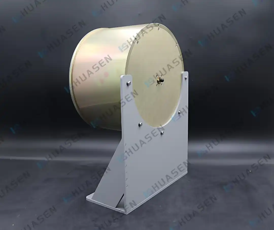
Key Advantages of Circular Polarization in Planar Helical Antenna Systems
When circular polarization is added to planar helical antenna systems, it gives them real operating benefits that directly address problems that telecom infrastructure providers, aerospace contractors, and defense system designers face. When these benefits are put into practice, they lead to higher system uptime, less upkeep work, and more organizational flexibility in difficult deployment situations.
Superior Multipath Rejection Performance
Base points in cities and at sea, using a planar helical antenna, are always fighting multipath interference, which weakens signals. When signals are sent and bounce off of objects like buildings, land, or the ocean, they arrive at antennas that are receiving them with different phase relationships and polarization states. When circularly polarized antennas receive these unwanted reflections, they block them because the handedness of the circular polarization changes when it is mirrored, turning an RHCP signal into an LHCP signal. The receiving antenna keeps its original polarization sense, so it naturally cuts these mirrored signals by 15–30 dB. This makes signal-to-noise ratios much better in RF settings with a lot of noise.
Orientation-Independent Signal Reception
Maintaining the best antenna alignment is always hard for satellite communication ground stations and aerial tracking systems. For linear polarization to work, the transmit and receive antennas must be perfectly lined up with each other; a mismatch of just 45 degrees can cause a 3 dB signal loss. This restriction is completely removed by circular polarization. The circularly polarized link keeps its coupling efficiency even if the receiving platform tilts, turns, or changes direction while in flight. This ability to work in any direction is very useful for systems that communicate with drones, LEO satellite ground stations, and mobile backhaul links, where adding mechanical pointing devices would make things too heavy and complicated.
Ultra-Wideband Coverage Capability
To cover the 0.2–18 GHz spectrum needed by current electronic warfare and signals intelligence tools, traditional narrowband antennas need more than one element or a complicated switching network. Due to their spiral shape, which is frequency neutral, planar helical antennas naturally provide multi-octave bandwidth. System designers choose a single antenna assembly that works with frequencies from L-band to Ku-band. This makes the RF front-end system a lot easier to understand. This combination cuts down on the number of parts that need to be kept on hand, gets rid of switching losses, and makes the system more reliable by getting rid of mechanical failure points. A normal VSWR of 2.5:1 or better across this whole bandwidth makes sure that power is transferred efficiently and that signal echoes are kept to a minimum, which keeps weak signals from being seen during reconnaissance operations.
Compact Footprint for Integration Flexibility
Aerospace and defense systems have to work within very strict weight and size limits. Traditional axial-mode helix antennas stick out a lot from their mounting surfaces, which can cause problems with radar cross-section and aerodynamic drag. Planar helical antenna designs fit snugly with equipment housings and keep low dimensions that are measured in millimeters instead of centimeters. This small shape makes it possible to place conformally on curved fuselage surfaces, shipboard masts, or equipment boxes where vertical space would normally make other antenna choices impractical. The smaller size also makes designing and covering the radome easier, which lowers the cost of production while increasing its weather protection.
Stable Gain and Radiation Characteristics
The antenna gain has a direct effect on the link budget calculations and sets the highest transmission range. Planar helical antennas have a modest gain level (−5 to 5 dB across their working bandwidth), but this gain is very stable no matter what frequency is used in the range given. Log-periodic arrays and other competing technologies have big changes in gain across their working bands, which makes designing automatic gain control for receivers harder. Planar helical systems can accurately plan coverage and analyze interference because their radiation pattern and beamwidth are always the same. System planners can safely guess how things will work without having to make a lot of field changes or set up compensation networks.
Because of these operating benefits, helical antenna-based antenna solutions are great for electronic support measures receivers, wideband direction-finding systems, and communications intelligence platforms that need to watch a lot of frequencies at the same time. The ability to use circular polarization makes it more likely that both intentional signals and accidental emissions will be picked up. This helps people with limited situational awareness in crowded electromagnetic settings.
Comparison with Alternative Antenna Types for Circular Polarization Needs
To choose the best radio technology, you need to know how the performance of different methods compares. There are different antenna designs that can create circular polarization, and each has its own pros and cons that make it better or worse for different uses.
Planar Helical versus Traditional Axial-Mode Helical Antennas
Since they were first made in the 1940s, three-dimensional helix antennas have been the best way to use circular polarization. These devices have great axial ratio performance and high gain, but they need a lot of space—usually many wavelengths long. Precision winding and maintaining helix wires is hard to do mechanically, which raises the cost of production and limits its ability to be scaled up.
Planar helical antennas have less gain than their axial-mode cousins, but they can do the same job in a package that is 80–90% smaller in volume. Automated PCB assembly methods are used in manufacturing to ensure tight tolerances on dimensions and great stability from unit to unit. The small size lets you set up arrays with multiple flat elements that work together to get gain levels that are the same as or higher than a single standard helical antenna while still having better bandwidth and being lighter.
Performance Comparison with Microstrip Patch Antennas
Microstrip patch antennas are the most common type used in GPS devices and cell phones because they have very low profiles and easy feed structures. Patch antennas need either two orthogonal lines with 90-degree phase shifters or patches that are specially made and have perturbation elements to make circular polarization. Both methods make things more complicated and greatly reduce the operating bandwidth—normally, circularly polarized patches work within a 2–5% fractional bandwidth.
Planar helical antenna systems can provide bandwidth ratios of 10:1 or more without the need for phase changers or matched networks. This bandwidth edge is very important for GNSS devices that handle multiple frequencies at the same time, like GPS, GLONASS, Galileo, and BeiDou, or for electronic warfare systems that keep an eye on threats across different frequency bands. Planar helical antennas have a better axial ratio bandwidth, which means that the polarization is pure across the whole working spectrum. Patch antennas, on the other hand, have a fast-decreasing axial ratio as you move toward the band edges.
Spiral Antenna Trade-offs
Archimedean spiral antennas have the same flat shape and wideband properties as planar helical antenna designs, but they don't have cavity backing, and they transmit in both directions. When only one-way coverage is needed, this two-way design doubles the antenna volume that needs to be used. This problem can be fixed with cavity-backed spiral antennas, but they usually have more gain changes across frequencies than flat helical designs because of cavity resonance effects.
The planar helical antenna's built-in absorbing cavity blocks backward radiation better and maintains a more stable input resistance over very wide bandwidths. This makes matching networks easier to use and makes it easier to predict how they will interact with nearby buildings or ground planes, both of which are important for dense equipment placements.
Conclusion
Planar helical antenna devices that provide circular polarization over frequency bands of 0.2 to 18 GHz meet important requirements in electronic warfare, satellite communications, and wideband tracking. Ultra-wide bandwidth, speed that doesn't depend on orientation, and small geometry all work together to give system builders strong tools for handling difficult RF integration problems. Planar helical designs have a wider bandwidth and more stable performance across all working frequencies than other technologies. They also have more manufacturable form factors that make them good for mass production. System integration goes smoothly when procurement strategies focus on technical standard alignment, environmental qualification testing, and the engineering skills of suppliers. As communication architectures change to support higher frequencies, wider bandwidths, and more complicated designs, planar helical antenna technology keeps getting better by using new materials and making the manufacturing process better. This makes these systems long-lasting solutions for tough RF applications.
FAQ
1. What frequency ranges do planar helical antennas typically cover?
Planar helical antennas are great for ultra-wideband tasks; in single units, they can usually handle frequencies from 0.2 GHz to 18 GHz. This bandwidth includes frequencies from L-band to Ku-band, allowing various transmission and surveillance bands to be used at the same time. Some custom designs can boost the range to 40 GHz or narrow it down to get the best gain and axial ratio for certain uses. Because spiral shape doesn't depend on frequency, it can achieve these amazing bandwidth ratios that can't be matched by other types of resonant antennas.
2. How does circular polarization improve signal reception quality?
When you rotate the antenna, circular polarization keeps the signal coupling the same. This means that you don't lose 3 dB or more like you do with misplaced linear polarization systems. Reflected signals change the handedness of the polarization, which lets receiver antennas block multipath interference by 15–30 dB. This mix of orientation freedom and multipath rejection greatly enhances signal-to-noise ratios in complex electromagnetic environments. This makes transmission more reliable and increases the chance of being picked up by electronic monitoring systems.
3. What installation considerations affect planar helical antenna performance?
To keep the radiation pattern from getting messed up, the opening area around the antenna face needs to stay clear during installation. At the lowest working frequency, metallic objects within one wavelength can cause reflections or pattern nulls that are not wanted. The backing cavity must stay properly sealed so that the absorber material keeps working well and water doesn't get in and hurt the electrical performance. Impedance matching is affected by the quality of the ground plane; VSWR degradation and pattern asymmetry are caused by ground links that aren't smooth or aren't joined well.
4. Can planar helical antennas handle high-power transmission applications?
The ability to handle power relies on the width of the wire trace, the breakdown voltage of the substrate material, and how well the heat is managed. Standard PCB fabrications can handle up to 50 watts of constant power, based on the duty cycle and frequency. For higher power uses, special materials are needed, such as PTFE that is filled with ceramics, thicker copper, and sometimes active cooling. Most planar helical antenna designs are used for receiving signals, where sensitivity and bandwidth are more important than power handling. However, custom designs can be made for situations where modest power transfer is needed.
Partner with Huasen Microwave for Advanced Antenna Solutions
The people at Huasen Microwave Technology have been designing and making high-frequency microwave and millimeter-wave parts for more than 30 years. Our Planar Helical Antenna systems have been shown to work well across the entire 0.2–18 GHz spectrum, with circular polarization purity that meets the most stringent needs for electronic surveillance and wideband tracking. Our ISO-certified facilities put every antenna through a lot of tests to make sure that the VSWR is less than 2.5 and that the gain stays the same across all operating bandwidths.
As a company that only makes Planar Helical Antennas, we can make them exactly how you want them, including changing the frequencies, the way they connect to other parts, and how they should be installed. Our engineering team helps with integration from the first idea to mass production. They do this by giving advice on designs, making sure simulations are accurate, and making fast prototypes. Contact our team at sales@huasenmicrowave.com to talk about how our antenna solutions can improve your system design when you need solid circular polarization performance in a small package with quick technical support.
References
1. Kraus, J.D. & Marhefka, R.J. (2002). Antennas: For All Applications, Third Edition. McGraw-Hill Education.
2. Nakano, H., Yamauchi, J. & Mimaki, H. (1988). "Backfire Radiation from a Monofilar Spiral Antenna with Normal and Reverse Rotations." IEEE Transactions on Antennas and Propagation, Vol. 36, No. 10, pp. 1359-1364.
3. Corzine, R.G. & Mosko, J.A. (1990). Four-Arm Spiral Antennas. Artech House Publishers.
4. Balanis, C.A. (2016). Antenna Theory: Analysis and Design, Fourth Edition. John Wiley & Sons.
5. Volakis, J.L. (2007). Antenna Engineering Handbook, Fourth Edition. McGraw-Hill Professional.
6. Kaiser, J.A. (1960). "The Archimedean Two-Wire Spiral Antenna." IRE Transactions on Antennas and Propagation, Vol. 8, No. 3, pp. 312-323.
Send Inquiry