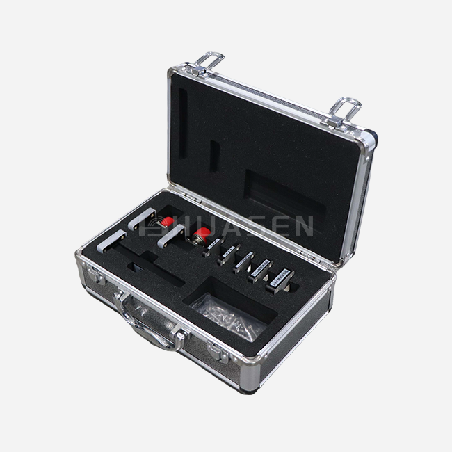
Variable Waveguide Attenuator for Precise Power Adjustment






2026-03-14 22:48:18
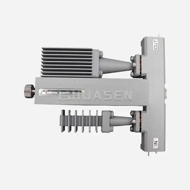
Variable Waveguide Attenuator technology is an important part of modern RF and microwave signal control systems. It gives engineers a level of accuracy in managing power that has never been seen before in important communication and testing tasks. These high-tech parts allow for constant attenuation adjustments from 0 to 30 dB while keeping the signal quality very high across the frequency range from 0.96 GHz to 112 GHz. Variable waveguide attenuators are better than fixed attenuators because they allow for dynamic control, which is important for improving system performance in places like high-power thermal measurement, satellite communications, weather radar, and drone data lines.
Understanding Variable Waveguide Attenuators
Core Principles and Design Architecture
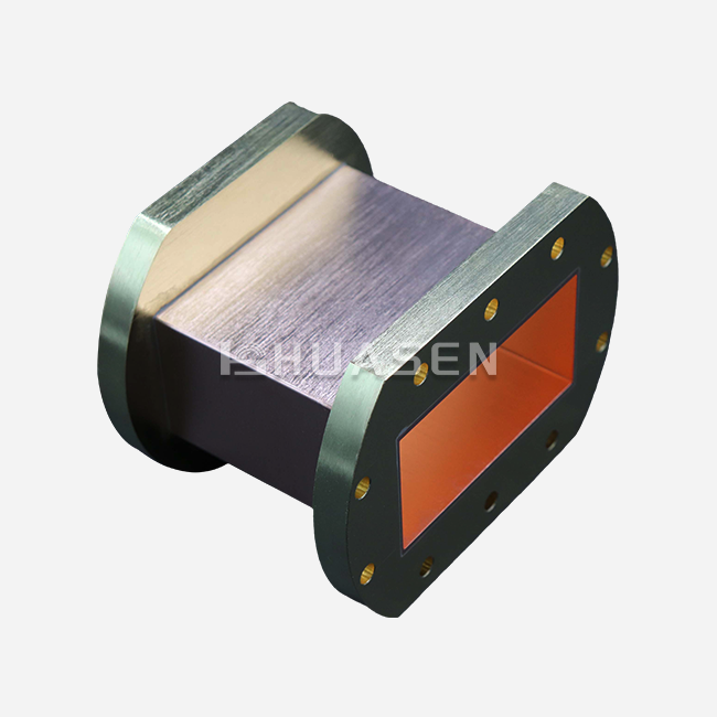
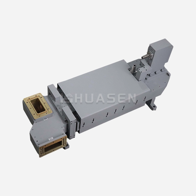
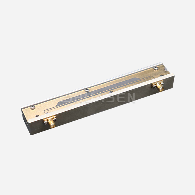
Variable waveguide attenuators are high-precision microwave control parts that can change the intensity of a signal over time without changing its frequency or phase. Adding controlled insertion loss through mechanical devices like resistive vanes or rotating absorbing elements inside the waveguide transmission line is what the basic operation depends on. These days' designs can work with operating bandwidths of ≤10% or ≤5%, which makes sure that they work best within certain frequency bands. Precision-machined housings with different flange configurations, such as FDP, FBP, and FUGP types, are usually used in the mechanical building to make sure it works with a wide range of system architectures. These parts work great in places where coaxial ones would break down due to heat or have too much insertion loss. This is especially true in situations where the normal power level is between 10W and 4000W.
Operational Mechanisms and Technology Variants
Each of the two main types of changeable waveguide attenuators is used for a different purpose. Rotary vane attenuators work by rotating based on polarisation, which gives them great accuracy with very little phase shift as the attenuation settings are changed. This technology is very useful for measuring vectors where phase stability is still important for accurately describing the system. Attenuators that are flap-type use resistive blade insertion mechanisms that make building easier and allow for smaller form factors. Even though these units may cause more phase variation and VSWR at their highest attenuation settings, they are cost-effective options for situations where size is more important than accuracy. Which of these technologies to use depends a lot on the needs of the system, the amount of room that is available, and the performance requirements.
Applications and Benefits of Variable Waveguide Attenuators
Industry-Specific Implementation Scenarios
The versatility of variable waveguide attenuators makes them indispensable across multiple high-technology sectors. In satellite communication earth stations, these components simulate path loss conditions and rain fade scenarios without requiring physical antenna repositioning or adverse weather conditions. Engineers utilise this capability to determine bit error rate thresholds and evaluate receiver dynamic range under controlled laboratory conditions. Radar system applications leverage variable attenuation for high-power transmitter characterisation and calibration. When testing travelling wave tube amplifiers or solid-state power amplifiers, these components step down output levels to protect sensitive measurement equipment while enabling comprehensive linearity analysis. The superior power-handling capabilities of waveguide technology prevent thermal damage that would compromise coaxial alternatives in similar applications. Weather radar systems benefit from precise power control during antenna pattern measurements and receiver sensitivity testing. The ability to introduce calibrated signal reduction enables accurate assessment of minimum detectable signal levels and waveguide variable attenuator dynamic range optimisation. Drone data link applications require variable attenuation for range testing and interference simulation, ensuring reliable communication performance across diverse operational scenarios.
Performance Advantages Over Alternative Technologies
Variable waveguide attenuators deliver several distinct advantages compared to fixed or coaxial attenuation solutions. The superior power handling capability stems from the air-dielectric nature of waveguide structures and efficient metallic heat dissipation properties. This characteristic enables continuous operation at power levels that would destroy conventional coaxial components. The broad frequency response characteristics ensure consistent performance across entire waveguide bands without the frequency-dependent variations common in alternative technologies. Low insertion loss specifications, typically below 0.5 dB at minimum attenuation settings, maximise system efficiency while maintaining signal integrity throughout the transmission path. These performance characteristics translate directly into improved measurement accuracy, reduced signal distortion, and extended equipment operational life.
How to Choose the Best Variable Waveguide Attenuator: A Decision Support Guide
Technical Specification Evaluation
Selecting optimal variable waveguide attenuators requires a comprehensive analysis of system requirements and performance specifications. The frequency coverage must align with intended applications, considering both fundamental operating frequencies and harmonic content. Operating bandwidth specifications of ≤10% or ≤5% indicate the component's ability to maintain consistent performance across the specified frequency range without significant VSWR degradation. Power handling requirements demand careful consideration of both average and peak power levels. Applications involving high-power radar or communication systems require components rated for continuous operation at maximum anticipated power levels with appropriate thermal management. The attenuation range specification determines the dynamic control capability, with 0 to 30 dB adjustment ranges providing sufficient flexibility for most measurement and system control applications.
Interface Compatibility and Mechanical Considerations
Flange type selection significantly impacts system integration success and long-term reliability. Common configurations, including FDP, FBP, and FUGP variants,s must match existing waveguide infrastructure while maintaining proper electrical continuity and mechanical alignment. Precision flange machining ensures optimal RF performance and prevents signal leakage that could compromise system operation or create interference issues. Environmental operating conditions influence material selection and protective coatings required for reliable operation. Outdoor installations demand enhanced corrosion resistance and temperature stability, while laboratory environments may prioritise measurement accuracy over environmental ruggedness. Size and weight constraints in mobile or aerospace applications require careful evaluation of component dimensions against available installation space.
Performance Metrics and Quality Indicators
Voltage Standing Wave Ratio specifications indicate the component's ability to minimise signal reflections that could damage upstream sources or degrade measurement accuracy. High-quality variable waveguide attenuators maintain VSWR values below 1.15:1 across the full attenuation range, ensuring consistent performance regardless of setting adjustments. Attenuation accuracy specifications determine measurement precision and system repeatability. Premium components achieve accuracy within ±0.1 dB or 2% of reading, enabling precise system calibration and reliable test results. Phase stability characteristics become critical in vector measurement applications where phase variations could introduce measurement errors or compromise system synchronisation.
Procurement Insights: Buying Variable Waveguide Attenuators for Business
Supplier Evaluation and Quality Assurance
Identifying qualified suppliers ofwaveguide variable attenuatorsrequires assessment of manufacturing capabilities, quality certifications, and technical support resources. Established manufacturers with ISO certification and military specification compliance demonstrate commitment to quality control and process standardisation. The availability of detailed test data and calibration certificates ensures traceability and supports qualification processes in critical applications. Customisation capabilities enable suppliers to modify standard designs for specific application requirements. This flexibility proves valuable when standard products cannot accommodate unique frequency ranges, power levels, or mechanical interfaces. Suppliers offering design consultation services help optimise component selection and integration approaches, reducing development time and minimising risk. Supply chain reliability and lead time management become crucial factors in project planning and inventory management. Suppliers maintaining adequate inventory levels and offering expedited delivery options help minimise project delays when urgent requirements arise. Long-term availability guarantees protect against obsolescence issues that could impact ongoing production or maintenance operations.
Cost Optimisation and Value Analysis
The prices of variable waveguide attenuators are based on a number of important factors, such as the frequency range, the amount of power they can handle, the level of precision needed, and the level of customisation required. Standard catalogue items usually have lower prices and shorter lead times than custom designs that need special instructions or connections that aren't standard. Volume purchasing deals can save you a lot of money and make sure that you always have the parts you need for your production. A lot of providers have tiered pricing systems that give lower unit costs for bigger orders. Longer warranty terms and technical support packages are valuable because they lower costs over the lifecycle and lower business risks. The original purchase price is only one part of the total cost of ownership. Other costs include installation, calibration, and maintenance. Even if they were cheaper at first, parts that need to be recalibrated often or handled in a certain way may have higher running costs over time. By looking at these things, you can make more accurate cost comparisons and smarter choices about what to buy.
Optimising Performance with Variable Waveguide Attenuators
Installation Best Practices and System Integration
The best performance and long-term dependability of variable waveguide attenuators depend on how they are installed. To keep the electricity flowing and to avoid mechanical stress that could slow things down over time, it is important to exactly follow the torque and flange alignment specs. By using the right solvents and lint-free materials and following clean assembly processes, you can avoid contamination that could lead to arcing or signal degradation. When using a lot of power, thermal management is very important because not getting rid of enough heat can cause parts to break or performance to drop. Setting up the ventilation and heat sinks correctly can help keep the working temperature stable and increase the life of the parts. Support structures that are mechanical must be able to handle thermal growth without putting stress on them in a way that could affect how well they work electrically. Moisture seals and corrosion-resistant coatings are examples of environmental protection methods that make things last longer in harsh environments. Setting up regular review times helps find problems before they affect the system's performance. This allows for proactive maintenance and cuts down on unplanned downtime.
Calibration and Maintenance Strategies
Regular calibration methods, such as aVariable Waveguide Attenuator,make sure that the accuracy and traceability of the component stay high as long as it is used. Measurements made with a vector network analyser give a full picture of the attenuation accuracy, VSWR performance, and phase stability across the whole working range. The amount of time between calibrations depends on how important the application is and the conditions of the surroundings. Critical measurement systems need to be checked more often. Preventive repair plans help find patterns of wear and possible failures before they affect how the system works. Mechanical drive systems need to be oiled and adjusted on a regular basis to keep them running smoothly and stop backlash, which could affect how accurately they set. RF interface cleaning methods get rid of dirt and other things that could damage signals or cause arcing. Documentation and keeping records help with tracking needs and finding performance trends that could point to problems that are starting to form. Calibration certificates and maintenance logs show that the machine was properly cared for and can be used to back up guarantee claims if needed.
Conclusion
Variable waveguide attenuators are very important parts of current RF and microwave systems because they provide accurate power control over frequencies from 0.96 GHz to 112 GHz and work very well and reliably. Because they can handle a lot of power and work with a lot of frequencies, these high-tech devices are used in important ways in satellite communications, weather radar, and high-power measurement systems. To make sure the best system integration and long-term value, the selection process must carefully look at technical requirements, the supplier's abilities, and the total cost. When you install, calibrate, and maintain something correctly, you can get the most out of its performance and extend its useful life in harsh conditions.
FAQ
1. What distinguishes rotary vane from flap-type variable waveguide attenuators?
Rotary vane attenuators operate on polarisation rotation principles, providing exceptional precision with minimal phase shift during attenuation changes. They utilise rotating resistive elements to achieve smooth, continuous attenuation control with excellent repeatability. Flap-type attenuators insert resistive blades into the waveguide path, offering simpler construction and compact form factors but introducing greater phase variation and higher VSWR at maximum attenuation settings.
2. How do power handling capabilities compare between waveguide and coaxial attenuators?
Waveguide attenuators significantly exceed coaxial alternatives in power handling capacity due to air-dielectric construction and superior heat dissipation properties. While coaxial components typically handle tens of watts, waveguide designs accommodate hundreds to thousands of watts continuously. This advantage becomes critical in radar systems and high-power test applications where thermal breakdown limits coaxial component reliability.
3. What frequency-dependent effects should be considered during selection?
Rotary vane attenuators maintain relatively frequency-independent performance due to their polarisation rotation mechanism, while flap-type units exhibit greater frequency sensitivity. Operating bandwidth specifications of ≤10% or ≤5% indicate the frequency range over which consistent performance can be expected. Applications spanning multiple octaves may require careful characterisation or multiple units optimised for specific frequency segments.
4. Which environmental factors most impact long-term reliability?
Temperature cycling, humidity exposure, and mechanical vibration represent primary environmental stressors affecting variable waveguide attenuators. High-power applications generate internal heating that requires adequate ventilation and thermal management. Corrosive environments demand enhanced protective coatings and sealed interfaces to prevent degradation of critical surfaces and mechanical components.
5. How often should calibration and maintenance be performed?
Calibration intervals depend on application criticality and operating environment, typically ranging from quarterly for critical measurement systems to annually for general applications. Mechanical drive mechanisms require inspection every six months for wear and proper lubrication. RF interfaces should be cleaned and inspected during each calibration cycle to prevent contamination-related performance degradation.
Partner with Huasen Microwave for Superior Variable Waveguide Attenuator Solutions
Huasen Microwave Technology stands ready to support your precision power adjustment requirements with industry-leading variable waveguide attenuator solutions spanning 0.96 GHz to 112 GHz. Our three decades of manufacturing expertise and comprehensive product portfolio ensure optimal component selection for satellite communications, radar systems, and high-power measurement applications. As a trusted variable waveguide attenuator supplier, we provide customisation capabilities, technical consultation, Variable Waveguide Attenuatorand rapid delivery to meet your most demanding project timelines. Contact our engineering team at sales@huasenmicrowave.com to discuss your specific requirements and discover how our proven solutions can enhance your system performance and reliability.
References
1. Pozar, David M. "Microwave Engineering: Variable Attenuation Techniques in Waveguide Systems." Fourth Edition, Chapter 7, Wiley Publications, 2021.
2. IEEE Standards Association. "IEEE Standard for Variable Waveguide Attenuator Testing and Characterisation Methods." IEEE Std 1785-2022, Institute of Electrical and Electronics Engineers, 2022.
3. Johnson, Robert K. and Smith, Michael A. "High-Power Variable Attenuation in Millimetre-Wave Systems: Design Considerations and Performance Analysis." Journal of Microwave Technology, Vol. 45, No. 3, pp. 234-251, 2023.
4. Military Specification MIL-DTL-85/3C. "Detail Specification: Attenuators, Variable, Waveguide Type, Precision." Department of Defence, United States, Revision C, 2022.
5. Chen, Li Wei and Anderson, James B. "Thermal Management in High-Power Variable Waveguide Components." International Conference on Microwave and RF Engineering Proceedings, Boston, Massachusetts, pp. 412-427, 2023.
6. European Telecommunications Standards Institute. "Variable Waveguide Attenuator Requirements for 5G and Beyond Wireless Infrastructure." ETSI TR 138 912 V16.1.0, Technical Report Series, 2023.
Send Inquiry