Low Noise Amplifier Applications in Satellite Communications






2026-07-22 17:04:17
Satellite communications demand extraordinary precision. Signals traveling thousands of kilometers from space arrive at ground stations weakened and fragile, barely distinguishable from background noise. The low-noise amplifier stands as the critical first stage in receiving chains, designed to boost these faint signals while adding minimal noise—a capability that directly determines whether satellite data reaches its destination intact or dissolves into static.
Understanding Low-Noise Amplifiers in Satellite Communications
Core Technical Principles
Every satellite receiver has to deal with the same basic problem: how to boost signals that are weak because of atmospheric attenuation and long transmission distances without making the signals worse. Low-noise amplifiers do this by carefully controlling three factors that are all connected to each other. The noise figure, which is usually given in decibels, tells you how much noise the amplifier itself adds to the signal. Gain controls how strong the signal is amplified. In modern satellite systems, gain ranges from 15dB to 50dB. Linearity makes sure that the amplifier correctly reproduces input signals without any distortion, even when it's working with more than one carrier at the same time.
The science behind satellite detection puts a lot of stress on these parts. Electronics thermal noise, atmospheric interference, and cosmic background radiation are all things that can interfere with the signal you want to send. A low-noise amplifier placed right after the antenna, before any wires or filters add more loss, picks up weak signals where they are greatest, keeping the signal-to-noise ratio stable throughout the receiving chain.
Frequency Band Considerations
Different types of bandwidth are used by satellite systems, and each one has its own problems with amplification. L-Band transmissions (1-2 GHz) work with cell phones and GPS and need low-noise amplifiers with noise levels of about 0.5 dB to 0.8 dB. Ku-Band downlinks (10.75 to 10.7 GHz) serve VSAT networks and broadcast TV, and our amplifiers can get noise levels as low as 1.3 dB. Ka-Band systems (26.5-40 GHz) allow high-throughput satellites for internet services. These systems need parts that are very stable at high temperatures and have very little phase noise.
| Frequency Band | Typical Range | Noise Figure Target | Common Applications |
|---|---|---|---|
| L-Band | 1-2 GHz | 0.5-0.8 dB | GPS devices and cell phones |
| S-Band | 2-4 GHz | 0.6-1.0 dB | Telemetry and communication between spacecraft |
| C-Band | 4-8 GHz | 0.7-1.2 dB | Services with fixed satellites |
| X-Band | 8-12 GHz | 0.8-1.5 dB | Radar and military communications |
| Ku-Band | 10.7-18 GHz | 1.0-2.0 dB | VSAT networks and broadcasting |
| Ka-Band | 26.5-40 GHz | 1.5-3.0 dB | Broadband satellites with high speed |
Design Essentials for Satellite Applications
Matching the impedance of radio feed systems and amplifiers has a direct effect on how well power is transferred. When matching isn't done right, echoes happen, which lowers gain and raises voltage standing wave ratio (VSWR), which hurts link costs. For outdoor installations, staying stable in temperatures ranging from -40°C to +85°C, you need to carefully choose the parts and set up thermal compensation circuits. Power use is important, especially for satellite packages, where every watt affects how much fuel is needed and how long the journey lasts.
Our engineering team solves these problems by making unique circuit designs that meet a lot of different needs. Distributed amplifier designs make the bandwidth bigger while keeping the gain response flat. At room temperature and above, noise input is lessened by newer GaAs and GaN semiconductor methods. In harsh deployment environments, hermetic packaging with N-type, SMA, K-type, or waveguide connectors keeps sensitive electronics safe from water, dust, and vibration.
Core Applications of Low-Noise Amplifiers in Satellite Communications
Ground Station Reception Systems
Earth stations are the most common place for satellite low-noise amplifiers to be used. These places get downlink signals that carry all kinds of things, from TV broadcasts to internet backhaul traffic. The amplifier is attached directly to the radio feed, which reduces connection loss before the amplifier. A normal C-band earth station with a low-noise amplifier that has 40 dB gain and a 0.9 dB noise figure can pick up signals 10 dB weaker than systems that use average amplifiers. This is the difference between systems that reliably receive signals and ones that frequently lose them.
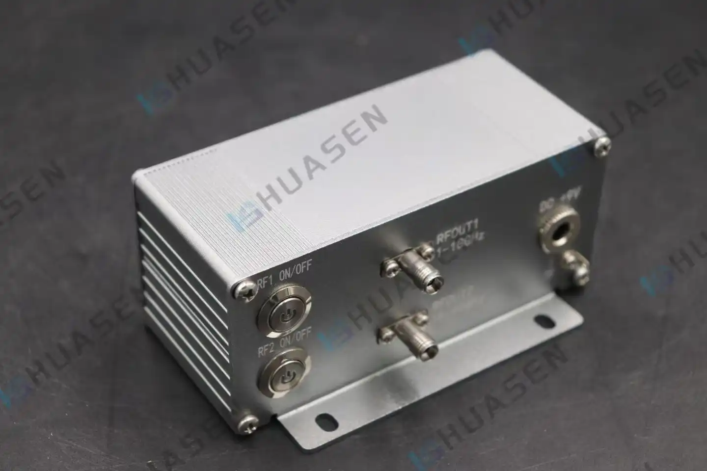
Teleport managers who are in charge of dozens of antennas have to deal with some unique organizational issues. When an amplifier fails, it affects thousands of end users, so dependability is very important. Standardized connector interfaces make replacements easy, and built-in bias protection circuits keep damage from lightning surges or antenna de-icing systems. Our AC Low Noise Amplifier line has built-in AC-DC power units that get rid of the need for external power sources and make installation easier in equipment racks that are already full.
Satellite Payload Integration
Uplink signals are amplified by transponders on board satellites before they are sent back to users on the ground. There are strict limits on power and weight. Each kilogram that is launched costs thousands of dollars, and the amount of electricity that can be used is limited by the capacity of solar panels. In this setting, low-noise amplifiers need to be very efficient, with noise levels often falling below 1.5 dB and power needs being less than 500 mW.
Radiation protection is very important for satellites that work in the Van Allen belts or beyond Earth orbit. High-energy particles slowly hurt semiconductor performance, changing the noise figure and gain over the lifetime of a mission. Low-noise amplifiers that are ready for space go through a lot of tests to make sure they still work after being exposed to a lot of radiation. They are designed to last 15 to 20 years in geostationary orbit.
VSAT Terminal Deployment
Very small aperture terminals connect remote areas to the internet via satellite where land-based infrastructure can't. VSAT is used for call, data, and video connections on ships, offshore platforms, in rural areas, and by emergency response teams. Small dish antennas, which are usually less than one meter in diameter, can only pick up a small amount of signal energy. This puts a lot of pressure on the low-noise amplifier's sensitivity.
I want you to look at an example from marine messaging. A shipping company replaced old Ku-Band ports with our low-noise amplifiers, which have a noise figure of 1.3 dB and a gain of 45 dB. The change made the carrier-to-noise ratio 3dB better, which let 40% more data pass through without needing bigger antennas or more send power. Within eight months, the equipment costs were covered by the fuel savings from better vessel routing using reliable connectivity, showing a clear return on investment.
How to Choose the Right Low-Noise Amplifier for Satellite Communications?
Critical Specification Parameters
To choose the right low-noise amplifiers, you need to make sure that the technical specs match the needs of the application. The amount of noise affects the receiver's sensitivity; for every 1dB drop, sounds twice as weak can be picked up. Gain has to be high enough to make up for losses in wires, filters, and later receiver stages, but not so high that it overloads mixers. The frequency response should match the satellite transponder assignments, with no gaps or too much roll-off at the edges of the bands.
| Parameter | Standard Low Noise Amplifier Range | High-Performance Range | Impact on System |
|---|---|---|---|
| Frequency of operation | 0.01 GHz to 100 GHz | Customisable | Finds out if the bands are compatible |
| Gain | 15 to 35 dB | 35 to 50 dB | Fixes losses in cables and parts |
| Noise Figure | 1.5 to 3.0 dB | 1.0 to 1.5 dB | Changes the receiver's sensitivity directly |
| Power Coming In (P1dB) | +5 to +10 dBm | +10 to +15 dBm | Keeps strong signals from overloading |
| How much power is used | 50–150 mW | 150–500 mW | Important for portable and space-saving uses |
| Temperature for Use | -20°C to +70°C | -40°C to +85°C | Adaptability to the environment |
When several satellites are in orbit close to each other, their ability to handle power is important. Strong signals from nearby transponders can cause low-noise amplifiers to compress, which creates intermodulation products that mess up the channels that are meant to be used. The 1dB compression point (P1dB) specification shows the highest input power that will not decrease gain. Higher numbers give better dynamic range in settings with a lot of noise.
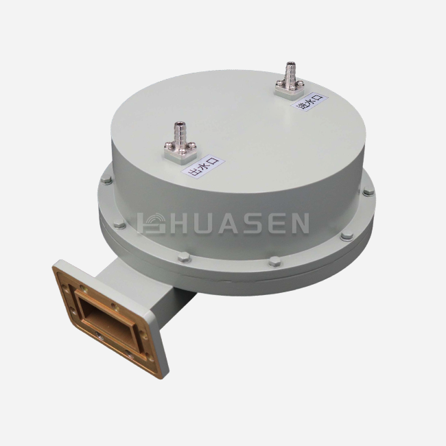
Different uses have very different physical size limits. Rack-mounted earth station amplifiers can handle complicated multi-stage designs, but micro-VSATs and payloads for robotic aerial vehicles need units that are much smaller. Compatible connectors make integration easier. Our product line has N-type interfaces for outdoor installations, precision SMA connectors for test equipment, K-type connectors for millimeter-wave uses, and waveguide flanges for high-power systems.
Distinguishing Component Functions
Purchasing managers sometimes mix up low-noise amplifiers with RF parts that are similar. Power amplifiers increase the strength of a signal before it is sent. They work at kilowatt levels, and their noise performance is less important than their uniformity and efficiency. Mixers change frequencies by mixing signals with nearby oscillators, which adds loss instead of gain. Filters let the frequencies you want through while blocking clutter. This adds insertion loss that low-noise amplifiers have to make up for.
Specification mistakes can be avoided by understanding these differences. For the satellite uplink to send signals to the spacecraft, it needs a power amplifier. For the downlink to receive weak return signals, it needs a low-noise amplifier. In order to receive satellite TV signals, low-noise block downconverters combine low-noise amplifier, mixer, and local oscillator functions, while block upconverters combine mixer and power amplifier functions.
Supplier Evaluation and Customization
Reputable makers show their knowledge by providing detailed datasheets that describe performance across a wide range of temperature, frequency, and power levels. Catalogue items from Mini-Circuits, Analog Devices, Texas Instruments, and Skyworks can be used in a lot of different situations. However, stock components rarely optimise all parameters at the same time; customisation is what's needed for a particular project.
Huasen Microwave Technology offers custom solutions for frequencies ranging from 0.01 GHz to 100 GHz. Engineering teams work directly with clients to change gain rates, connector types, or weather protection, or to create multi-band designs that cover frequency allocations that are not adjacent. Bulk procurement plans lower the cost per unit for large operations while keeping the quality standards that have been built up over 30 years of making RF components.
Benefits and Challenges of Using Low-Noise Amplifiers in Satellite Communications
Link Budget Enhancement
Link costs are very important in satellite communication systems because they work at the edge of physics. By switching from a low-noise amplifier with a noise figure of 2.0 dB to our 1.3 dB solution, the receiver's sensitivity goes up by 0.7 dB, which doesn't seem like much until you think about it in real life. This improvement increases the coverage area by 8%, lowers the size of the antenna that is needed by 12%, or lets you use advanced modulation schemes to get 15% faster data rates. These improvements add up to big advantages for operators who are in charge of hundreds of terminals.
Bit error rates and service quality are based on how well signals are sent and received along all receiving lines. When handling multiple carriers, low-noise amplifiers with better uniformity reduce intermodulation distortion, which is very important for frequency reuse schemes that make the most of satellite capacity. Third-order intercept point (IP3) standards measure this behavior; higher values mean better handling of multiple carriers without creating unnecessary signals.
Environmental and Operational Challenges
Changes in temperature can change how semiconductors behave, moving the noise figure and gain away from what they should be at room temperature. Salt spray can damage buildings near the coast, ice can build up on mountaintops, and 60°C temperature changes during the day can happen in the desert. Our designs are hermetically sealed and have conformal coatings that protect the circuitry while keeping thermal paths open so that heat can escape.
Performance doesn't change over weeks or months of ongoing running when bias is stable. When voltage regulators aren't very good, they add source noise that changes the gain of the amplifier and makes false signals that lower carrier-to-noise ratios. We use temperature-compensated bias networks and multi-stage filtering to keep specs the same over the lives of components that last more than 100,000 hours on average before they break.
Emerging Technology Trends
For next-generation satellite constellations to work in low Earth orbit, new rules need to be followed. Doppler changes are caused by fast satellite motion and need bigger bandwidth coverage. When phased array antennas track multiple satellites at the same time, they need small low-noise amplifier units that can fit behind each radiating element. Ka-Band and V-Band bands allow terabit-per-second throughput, which is moving component development toward millimeter-wave frequencies, which is where our designs with waveguides built in work best.
By processing L-, Ku-, and Ka-Band signals through shared antennas and receivers, multi-band operation makes ground infrastructure easier to set up. Because of this change in architecture, there is a need for a broadband low-noise amplifier that can maintain specifications across octave bandwidths. This is an area where customization is very important. This combination is not often found in standard catalogue parts, so engineering partnerships are very important for successful deployment.
Conclusion
Reliable satellite communications are built on low-noise amplifiers, which turn signals that are too weak to be used into usable data. Their efficiency directly affects how sensitive the receiver is, how much area it covers, and how much data it can send and receive between ground stations, satellite packages, and VSAT terminals. To choose the right devices, you have to find a balance between noise figure, gain, frequency response, and environmental resilience, while also taking cost structures and supplier reliability into account. Low-Noise Amplifier innovation keeps making connections better for defense systems, marine operations, telecommunications, and global broadband access as satellite technology moves toward higher frequencies, bigger bandwidths, and constellation designs.
FAQ
1. What noise figure should I target for satellite communication LNAs?
The target noise levels rely on the frequency band and how important the application is. For the best response, L-band low-noise amplifiers need 0.5 to 0.8 dB. Ku-Band usually needs 1.0 to 2.0 dB, while Ka-Band can handle 1.5 to 3.0 dB because atmospheric loss takes up most of the link budget. Premium ultra-low-noise designs are needed for important military or deep-space transmissions, but commercial broadcasts can handle slightly higher figures with bigger antennas.
2. Can general-purpose LNAs replace satellite-specific designs?
Most general-purpose amplifiers don't have the qualities that are needed for satellite uses. They might not have the weatherproof ports that are needed for outdoor setups, they might not have temperature adjustment, which could cause performance to slip, or they might not have enough gain flatness across transponder bandwidths. Satellite-optimized low-noise amplifiers have features that regular laboratory amplifiers don't have, like impedance matching for standard feed systems, bias safety against antenna control voltages, and an increased dynamic range for multi-carrier environments.
3. How does LNA gain affect overall signal reception quality?
Higher gain raises the signal levels that reach later receiver stages, but it doesn't make the system more sensitive past the point where noise from the amplifier takes over. Too much gain can make mixers unstable or overloaded. The best gain levels compensate for cable losses and give demodulators enough signal power—usually 30 to 45 dB is enough for most setups. If you want to improve your ability to receive weak signals, put a low-noise figure ahead of maximum gain.
Partner with Huasen Microwave for Superior Satellite LNA Solutions
Huasen Microwave Technology creates designed amplification solutions that meet the strict needs of global satellite communications. Our wide range of products covers frequencies from 0.01 GHz to 100 GHz, with gain options from 15 dB to 50 dB and noise levels as low as 1.3 dB. These specs will directly improve your link budgets and system reliability. We make normal low-noise amplifier setups as well as AC-integrated models with built-in power units that work with N-type, SMA, K-type, and waveguide connectors so they can fit your system.
With more than 30 years of experience working with RF components, we offer full customization services that take into account specific frequency licenses, weather-hardening needs, and mechanical integration limitations. Our engineering team works together closely to make sure that your satellite ground stations, VSAT terminals, or payload systems work at their best during design creation, prototype testing, and large-scale production. Email our technical sales specialists at sales@huasenmicrowave.com to talk about the needs of your project, get detailed datasheets, or set up an evaluation sample. We are a reliable low-noise amplifier seller to research institutions, defense contractors, and telecommunications companies. We are dedicated to providing you with high-quality parts that improve your satellite communication.
References
1. Gilmore, R., & Besser, L. (2020). Practical RF Circuit Design for Modern Wireless Systems: Active Circuits and Systems. Artech House Publishers.
2. Maas, S. A. (2019). Noise in Linear and Nonlinear Circuits. Artech House Microwave Library.
3. Sayre, C. W. (2018). Complete Wireless Design (3rd ed.). McGraw-Hill Education.
4. Pozar, D. M. (2021). Microwave Engineering (5th ed.). Wiley.
5. Vendelin, G. D., Pavio, A. M., & Rohde, U. L. (2017). Microwave Circuit Design Using Linear and Nonlinear Techniques (2nd ed.). Wiley-Interscience.
6. Gonzalez, G. (2018). Foundations of Oscillator Circuit Design. Artech House Publishers.
Send Inquiry