How Impedance Mismatch Is Solved by Waveguide Transition Designs






2026-07-06 18:45:02
Impedance mismatch is a major problem in RF and microwave systems that has a direct effect on data quality and system stability. By acting as precisely designed impedance transformers that connect various transmission media, waveguide transition designs address this crucial problem. To match the characteristic impedance between the source and load, these parts use curved shapes or stepped internal structures, like Chebyshev or Binomial multi-section matching. Waveguide transitions keep energy efficiency high along the whole transmission path by gradually changing cross-sectional dimensions and electrical properties. This reduces signal reflections, raises the Voltage Standing Wave Ratio (VSWR), and keeps the transmission path as energy-efficient as possible in demanding applications like radar systems and satellite communications.
Understanding Impedance Mismatch and Its Impact in Waveguide Systems
What Causes Impedance Mismatch in RF Transmission?
Impedance mismatch happens when electromagnetic energy hits sudden changes in the qualities of a transmission line. In high-frequency systems, the different sizes of coaxial cables and waveguides cause breaks in the signal that send parts of the signal back to the source instead of sending them forward. Differences in materials, like copper versus aluminum building, changing dielectric qualities, or changes in surface roughness, can all affect the effective impedance at the junction point.
Behaviors that depend on frequency make these problems a lot more difficult to solve. As the working frequencies rise into the millimeter-wave range, even small changes in shape become electrically significant. When bands get shorter and tolerances get tighter in the Ka-band, a link that works fine in the X-band may not work at all in the Ka-band.
Consequences of Unresolved Impedance Discontinuities
Mismatched impedances cause system performance to drop in many ways when they are not fixed. When insertion loss goes up, valuable transmission power is wasted. This is a big problem in satellite uplinks, where even the smallest changes in volume are important. A high VSWR number means that a lot of energy is being returned, and this energy builds up as standing waves inside transmission lines. This mirrored power heats up parts, which could hurt sensitive amps like Klystrons or Solid State Power Amplifiers that cannot tolerate reverse power loads.
Reflections change the phase and intensity of signals across the working bandwidth, which is bad for signal integrity. When used in radar, these artifacts make it harder to see targets clearly. When the signal-to-noise ratio goes down, bit error rates go up in communication systems. Also, breaks in the resistance can cause parasitic higher-order modes to excite. These are unwanted electromagnetic field patterns that mess up the signal you want to send and cause interference.
Business Impact on System Integrators and Equipment Manufacturers
When impedance mismatch isn't fixed, procurement teams and system designers have real problems to deal with. When equipment fails in deployed base stations, expensive field service calls and new packages are needed. When test fixtures bring unknown mismatch errors, they make it hard to get accurate readings in the lab and stay in line with ISO 17025 standards. When parts have poor VSWR performance, production yields go down, and reject rates and stocking costs go up. Longer approval tests are needed to make sure the system works reliably in the real world, which delays the start of the project and the entry into the market.
Principles Behind Waveguide Transition Designs to Eliminate Impedance Mismatch
How do transitions bridge different transmission media?
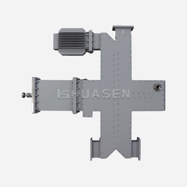
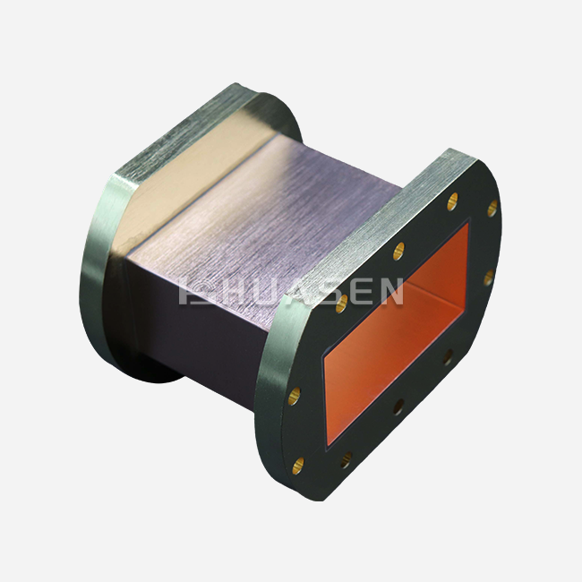
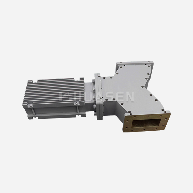
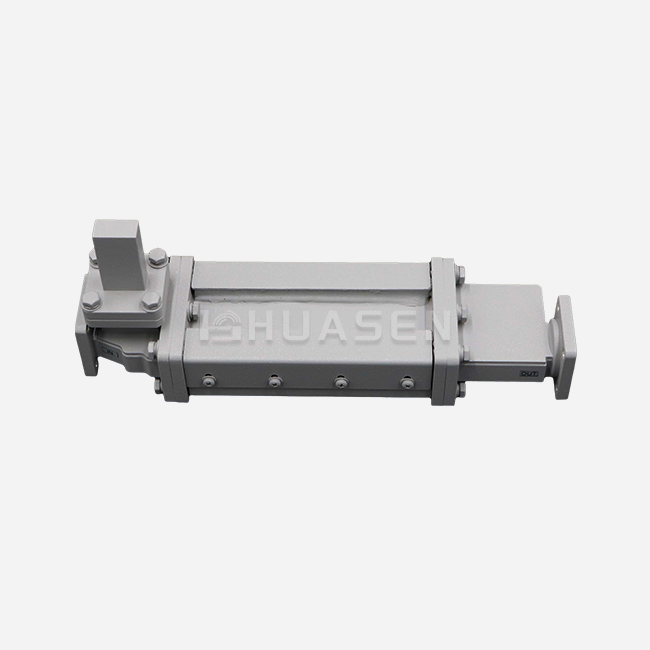
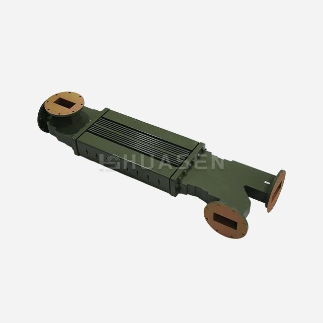
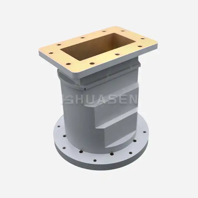
Waveguide transitions are special impedance transformers that connect different RF parts while keeping the signal's purity. The basic idea is that geometric shapes should change gradually instead of quickly. A coaxial-to-waveguide adapter is often used in test sets. It extends a center wire into the waveguide cavity while the probe depth and position are carefully managed to couple energy efficiently into the dominating TE10 mode. Waveguide-to-waveguide transitions connect different cross-sections, like WR-137 to WR-112, with tapered parts that change the width and height of the waveguide in a smooth way over a determined length.
Circular waveguide transitions take care of the need for polarization variation in antenna feeds. These parts change waveguide modes from rectangles (TE10) to circles (TE11), which lets the polarization plane rotate for uses like dual-polarization weather radars. Round guides are great for connecting antennas on towers because they are rotationally symmetrical, which lowers loss over long transmission runs.
Design Parameters That Determine Transition Performance
Several engineering factors affect how well a shift works. The length of the taper has a direct effect on the bandwidth. Longer gradual tapers offer wider working ranges with less reflection, while compact designs give up bandwidth to be smaller. At microwave frequencies, where skin effect limits current flow to the conductor surface, the quality of the finish on the surface becomes very important. When the internal roughness is more than 63 micro-inches, resistance losses go up. This is especially true above 40 GHz, where surface currents tend to gather in smaller layers.
The choice of material strikes a balance between conductivity, weight, and resistance to the surroundings. Oxygen-Free Hard Copper (OFHC) is the most conductive material for lab-grade changes, and it keeps insertion loss below 0.1 dB. When compared to copper, aluminum alloy 6061-T6 is about 70% lighter, which makes it important for uses in spaceships and aircraft where every gram counts. Protective covering, like silver or gold according to MIL-G-45204, stops oxidation that would otherwise weaken transmission over time, especially in humid marine settings.
Matching Techniques: Tapered Versus Stepped Designs
There are two main physical ways to match the resistance. To show gradually changing resistance along the transmission path, tapered transitions use continuous changes in dimensions, such as linear, exponential, or optimized patterns like Klopfenstein tapers. With this method, you can get great wideband performance, often covering whole waveguide bands with VSWR below 1.15:1, but the actual length has to be longer.
Stepped transitions use the idea of quarter-wave transformers to make separate impedance parts that work together to make the desired matching characteristic. Chebyshev designs try to get the ripple properties to be as good as possible across the passband. This allows for smaller housing, but the working bandwidth is narrower. When it comes to reflection, binomial answers aim for the highest bandwidth and smoother behavior, but they usually need more parts to achieve the same level of performance. Engineers choose one of these methods over the other based on available room, frequency coverage needs, and the amount of VSWR that is acceptable for the application.
Comparing Waveguide Transitions with Other Solutions: Making an Informed Choice
Performance Metrics: VSWR, Insertion Loss, and Power Handling
Understanding the most important specs helps buying teams compare different options in a fair way. VSWR measures how well two impedances fit. Values below 1.20:1 mean great performance for sensitive applications, while rates up to 1.35:1 might be enough for less demanding systems. Precision metrology-grade transitions get the VSWR below 1.10:1, which is necessary for calibrating a vector network analyzer where measuring error needs to be kept to a minimum.
Insertion loss tracks how much the signal is weakened during the shift. The loss in air-dielectric waveguide systems is very low, usually between 0.1 and 0.3 dB, based on the frequency and length of the guide. Coaxial options have more loss because the insulating materials they use are different and the conductors they use are smaller. Waveguide solutions are much better at handling power than coaxial connections. Air breakdown voltage limits let kilowatt to megawatt peak power levels, but coaxial connectors rarely handle more than hundreds of watts before dielectric heating or arcing happens.
Rigid Versus Flexible Waveguide Considerations
Mechanical format choices are often based on how the system is installed. With less insertion loss and more power capacity, rigid waveguide transitions offer better electrical performance. Their solid metal design keeps their shape even when heated and cooled, and when they are vibrated, meeting MIL-STD-810 standards for defense uses. Rigid designs, on the other hand, need to be perfectly lined up when they are installed and can't be moved or bent.
Flexible waveguide transitions (circular waveguide transitions) have metal parts with ridges that let you bend them and move them around. This adaptability makes installation easier in small areas where set lines wouldn't work, like when connecting gimballed radar antennas that spin while they're working. In exchange, there is a little more insertion loss, usually an extra 0.2 to 0.5 dB, because there is more surface area and possible mode conversion at bends. Power handling also goes down compared to fixed parts of the same type, but it's still much better than coaxial options.
Alternative Matching Approaches and Their Limitations
Coaxial connectors are easy to use and widely available, but they have a lot of problems at higher frequencies. When the frequency goes above 18 GHz, cable parts lose more signal and become more fragile. Connector consistency, which is the change in electrical performance that happens after multiple joining cycles, makes test measurements less accurate. The insulating materials needed for coaxial building limit the range of temperatures and cause thermal drift.
Impedance matching networks with separate parts like capacitors, inductors, and transmission line pieces might be able to match at certain frequencies, but they don't have the wide range of performance and power handling that waveguide transitions do by design. These lumped-element methods also add more places where things can go wrong and make mechanical packaging in small parts more difficult.
Procurement Considerations for Waveguide Transitions: What B2B Buyers Need to Know?
Cost Factors: Custom Versus Standard Catalog Products
Pricing models are very different depending on how complicated the plan is and how many are being made. Standard waveguide transitions with popular flange types (CPR, UG, and UBR) and well-known frequency bands can be made using standard methods, which results in lower unit costs and faster lead times. Components in the catalog for X-band, Ku-band, and Ka-band use usually ship within two to four weeks from reputable sources.
Custom transitions that meet specific system needs, like non-standard frequency ranges, custom flange connections, or specific environmental standards, need engineering design processes and the purchase of tools. Simulations and measurements are used in the prototyping process to make sure that the electromagnetic performance is good before committing to production amounts. Even though custom development costs more up front and takes longer to deliver (up to eight weeks or more), the parts that are made often work better than standard goods. When you buy more than a few dozen units, the price per unit goes down because the cost of the tools is spread out over the whole production run.
Supplier Selection Criteria and Certification Requirements
Trustworthy providers show qualities that can be measured that go beyond low prices. Manufacturing certifications like ISO 9001 show that there are well-established quality control systems that always make sure that goods meet standards. MIL-DTL-85 compliance is needed for defense and aircraft uses to make sure that changes can handle certain levels of shock, vibration, and environmental extremes. RoHS approval handles environmental rules that are needed for markets in Europe and are becoming more and more important for distribution around the world.
The ability to customize sets key partners apart from commodity sellers. Manufacturers with a lot of experience keep engineering teams that can use tools like HFSS or CST Microwave Studio to simulate electromagnetic fields. This lets them make changes to designs quickly and improve performance. Product paperwork that includes S-parameter files, mechanical models with tolerance details, and test data showing real VSWR and insertion loss across frequency makes it possible to confidently integrate into bigger systems without having to go through a lot of qualification testing.
Best Practices for Specification Communication
When you have clear technical needs, it's easier to buy things (circular waveguide transition), and less time is spent on revisions. There should be clear limits on the operating frequency range and passband, as well as limits on acceptable VSWR and insertion loss. There should also be requirements for power handling (both average and peak), flange standards with clear UG or CPR designations, and environmental conditions that include temperature range, humidity exposure, and vibration profiles. Mechanical limitations, such as package sizes, weight limits, and mounting options, stop designs that truly can't fit into target systems.
During the quote phase, procurement managers ask for basic performance data to speed up project timelines. If a supplier has done similar designs before, they can often guess what standards will be possible and point out any problems that might come up before official orders are placed. Sample evaluation tools let you try prototype units in real system setups to make sure they work well and are compatible before committing to large-scale production. This iterative method lowers risk and boosts trust in the supplier's abilities.
Conclusion
Impedance mismatch hurts the performance of an RF system by reflecting signals, causing more loss, and possibly damaging parts. Waveguide transition designs get around these problems by using curved or stepped shapes that change the resistance between different types of transmission media gradually. To make the right choice, you need to weigh mechanical factors like size, weight, and environmental resistance against electrical performance measures like VSWR and insertion loss. To be successful at procurement, you need to be able to communicate clear specifications, evaluate suppliers, and know how much unique versus standard solutions will cost. In the real world, designed changes that meet the needs of specific applications have led to measured performance gains in areas like satellite communications, aerospace radar, and industrial tracking.
FAQ
1. What frequency ranges do standard waveguide transitions cover?
Standard changes line up with well-known waveguide bands that go from L-band to W-band (1 GHz to 110 GHz). WR-650 for L-band (1.11–1.70 GHz), WR-137 for C-band (5.85–8.20 GHz), WR-90 for X-band (8.20–12.40 GHz), WR-62 for Ku-band (12.40–18.00 GHz), and cross-sections getting smaller all the way up to millimeter-wave frequencies are common. It is assured that each common waveguide size will work with a certain frequency range and meet certain power handling requirements.
2. Can waveguide transitions be customized for unique system requirements?
Manufacturers with a lot of experience often change the shifts to solve specific technology problems. Customization includes non-standard frequency ranges, custom flange connections, materials made for harsh environments, built-in filter functions, and small packaging for setups with limited room. Before committing to production, the development method includes electromagnetic modeling, making a prototype, and testing its performance. Custom designs usually take eight to twelve weeks to deliver for the first time, and the engineering costs are spread out over the number of items that are made.
3. How is transition effectiveness measured after installation?
Performance evaluation employs measurements taken with a vector network analyzer that record S-parameters over the working frequency range. S11 measures the amount of power that is returned and gets VSWR, and S21 measures the efficiency of the gearbox. To get exact results from measurements, test fixtures must be calibrated and have known reference lines. When performance is good, the VSWR is within the range specified in the datasheet (typically <1.25:1), and the insertion loss is within the acceptable range (usually <0.3 dB). Time-domain reflectometry can help you find specific differences when you're trying to figure out why something isn't working right.
Partner with Huasen Microwave for Precision Impedance-Matching Solutions.
When it comes to difficult waveguide transition tasks, Huasen Microwave Technology brings 30 years of RF technical experience to the table. Our production skills include both regular catalog items and designs that are completely unique and made to fit your system. Our engineering team creates solutions that are the best in terms of performance, dependability, and cost, whether you need coaxial-to-waveguide adapters for test setups in the lab, high-power transitions for base station infrastructure, or climate-hardened parts for flight platforms.
As a well-known company that makes Waveguide Transitions, we keep high-quality standards by being certified by ISO 9001 and following MIL-DTL-85 for defense uses. Our design method uses advanced electromagnetic simulations that have been checked by thorough testing to make sure that the VSWR, insertion loss, and power handling performance meet the requirements. Get in touch with our technical sales team at sales@huasenmicrowave.com to talk about your impedance matching needs and get full quotes that come with clear paperwork and quick engineering support.
References
1. Pozar, David M. "Microwave Engineering, Fourth Edition." John Wiley & Sons, 2011.
2. Collin, Robert E. "Foundations for Microwave Engineering, Second Edition." IEEE Press, 2001.
3. Balanis, Constantine A. "Advanced Engineering Electromagnetics." John Wiley & Sons, 2012.
4. Saad, Theodore S. "Microwave Engineers' Handbook, Volumes 1 and 2." Artech House, 1971.
5. Marcuvitz, Nathan. "Waveguide Handbook." MIT Radiation Laboratory Series, McGraw-Hill, 1951.
6. Montgomery, C.G., Dicke, R.H., and Purcell, E.M. "Principles of Microwave Circuits." MIT Radiation Laboratory Series, Dover Publications, 1948.
Send Inquiry