What are the main structural types of electric waveguide switches and what are the differences in their working principles?






2025-11-09 21:20:08
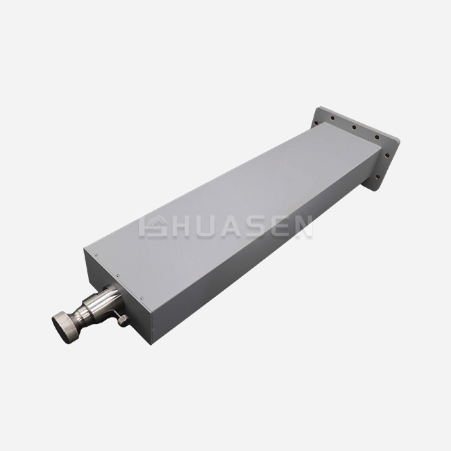
Electric waveguide switches are key components in high-frequency scenarios such as microwave communication and radar systems. In high-frequency application scenarios, as the core signal path control device, the structural design and working principle of electric waveguide switches directly affect the transmission efficiency and reliability of the system. Huasen Microwave Technology Co., Ltd., a company focusing on the research and development of microwave devices, divides electric waveguide switches into structural types such as single-pole single-throw (SPST), single-pole double-throw (SPDT), and multi-pole multi-throw (MPnT) based on the needs of different application scenarios. Through modular architecture, precision manufacturing processes, and intelligent drive control, it meets the application needs of different scenarios. This article will introduce in detail the main structural types of electric waveguide switches and conduct an in-depth analysis of the core differences in their working principles.
Core structure types of electric waveguide switches
The electric waveguide switch products of Huasen Microwave are mainly classified in terms of structure from two dimensions, which cover both the differences in the plane of electromagnetic field action and the differences in the configuration of functional ports, forming a diversified product matrix.
Classified by structural form: E-plane and H-plane waveguide switches
This classification is based on the differences in the principal planes of electromagnetic fields during microwave signal transmission. As the most fundamental structural classification method for electric waveguide switches, it directly determines their applicable scenarios and performance characteristics.
-
E-plane Waveguide Switch
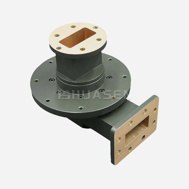
E-plane waveguide switch features switching action on the E-plane (parallel to the electric field direction). Its structural design is compatible with two mainstream waveguide types—rectangular waveguides and double-ridged waveguides—allowing flexible selection based on different frequency bands and power requirements. With a compact transverse layout (size compressed along the electric field direction), it excels in space-constrained scenarios such as integrated microwave modules and miniaturized radar systems. The mechanical structure prioritizes lightweight design and fast switching response, making it ideal for equipment demanding high space utilization.
- H-plane Waveguide Switch
H-plane waveguide switch focuses its switching process on the H-plane (parallel to the magnetic field direction). It is also compatible with rectangular and double-ridged waveguides, and demonstrates more stable phase consistency and low insertion loss in high-frequency signal transmission (e.g., millimeter-wave and submillimeter-wave bands). Owing to the structural properties of the magnetic field principal plane, its longitudinal layout (extended along the magnetic field direction) effectively reduces electromagnetic wave reflection during high-frequency signal processing, making it particularly suitable for high-end scenarios with strict requirements for phase stability and signal integrity, such as phased array radars, satellite communications, and high-precision measuring instruments.
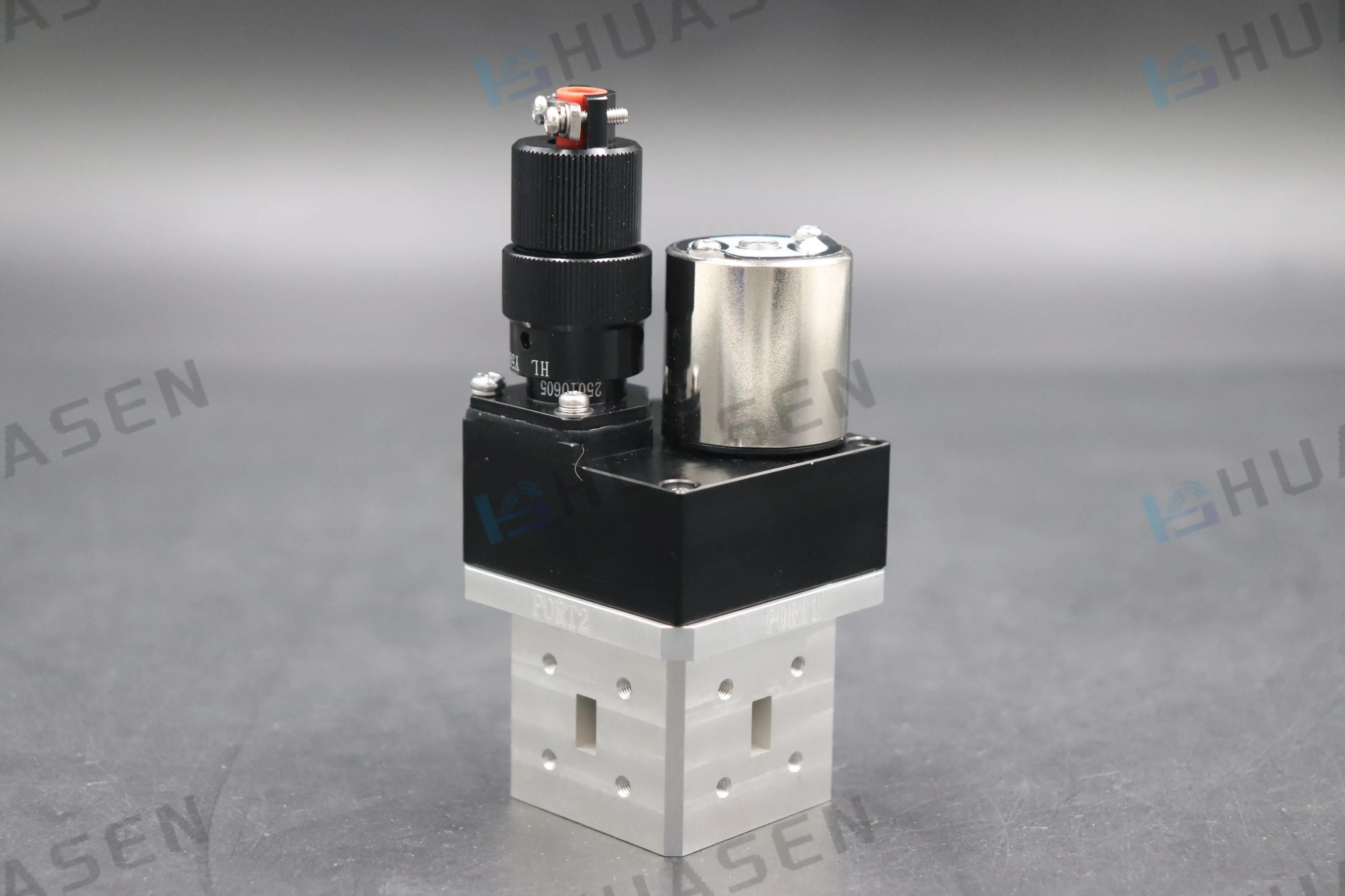
Classification by functional configuration: Port switching structure translation
According to the requirements for signal path control in practical applications, electric waveguide switches have developed a variety of functional configurations through the design of port quantities and switching logics, so as to meet the signal routing needs of systems ranging from basic to complex ones.
-
Single Pole Double Throw (SPDT)
One-input two-output port switching structure adopts a basic "one-input and two-output" layout, composed of 1 input port (common port) and 2 output ports (selectable ports). Its switching principle relies on a motor to drive the internal waveguide rotor to rotate or the sliding block to translate, thereby realizing the selective connection between the input port and one of the two output ports (e.g., "input → output 1" or "input → output 2"). As the most basic and widely used structural type, it is suitable for simple signal switching needs, such as transmit-receive switching in communication systems, path selection in test equipment, and single-target signal routing in radar systems.
-
Double Pole Double Throw (DPDT)
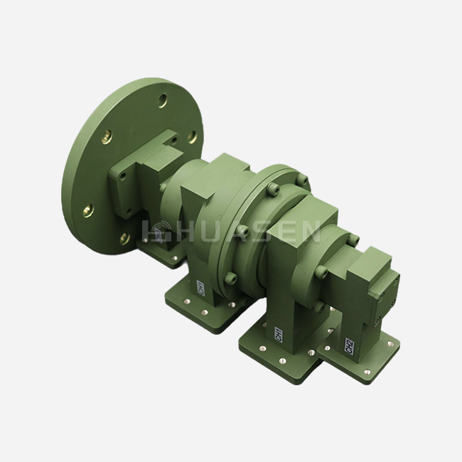
Two-channel synchronous port switching structure features two independent signal control channels, consisting of 2 input ports and 4 output ports (each channel corresponds to a "one-input and two-output" structure). Its switching principle involves a motor driving and synchronously controlling two sets of independent switching mechanisms, enabling simultaneous switching of two "one-input and two-output" signal paths (e.g., "input 1 → output 1-1, input 2 → output 2-1" or "input 1 → output 1-2, input 2 → output 2-2"). This structure is suitable for complex systems requiring synchronous control of multiple signal paths, such as multi-band communication equipment, dual-polarized antenna systems, and subarray signal distribution in phased array radars, effectively enhancing system integration and control efficiency.
-
3-Channel 6-Port (3×2 Matrix Switch)
Multi-port matrix switching structure adopts a multi-port matrix design, typically consisting of 3 input ports and 6 output ports (or 3 groups of "one-input and two-output" channels), supporting independent or coordinated switching of three signal paths. Its switching principle relies on the coordinated driving of multiple motors or a complex cam structure, enabling "one-input and two-output" switching of a single signal path, cross-switching of multiple signal paths (e.g., input 1 → output 2-1, input 2 → output 3-2, etc.), and even simultaneous connection of some ports (provided system isolation requirements are met). This structure meets the needs of high-end application scenarios such as multi-channel communication, multi-target detection, and multi-band signal processing, with typical applications including multi-terminal signal distribution in satellite communication ground stations, multi-target jamming signal routing in electronic warfare systems, and signal switching in multi-channel spectrum analyzers.
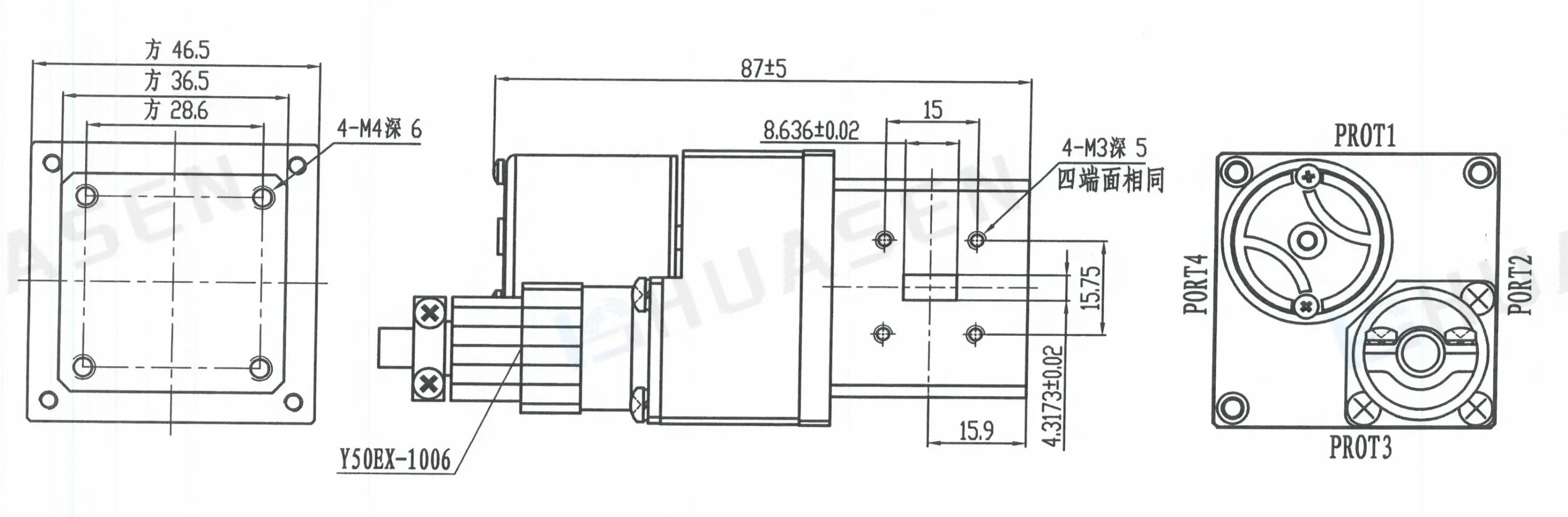
Analysis of the core differences in working principles
The differences in the working principles of electric waveguide switches are mainly concentrated in two aspects: the interaction mode of the electromagnetic field and the coordination with mechanical drive. Among them, the principle differences between E-plane and H-plane switches are the most significant.
The difference in the effects of electromagnetic field distribution
When microwave signals propagate in waveguides, the electromagnetic field exhibits specific distribution patterns, and the structural design of the switch directly determines how it guides the electromagnetic field:
E-plane switch: The switching action focuses on the main plane of the electric field, where the direction of the electric field remains parallel to the branch arms of the switch. Its core mechanism involves moving a metal plate to alter the transmission path of the electric field. By utilizing the metal plate to block or conduct the electric field, it achieves the switching of signal paths. This method ensures that the electric field distribution maintains stability more easily during switching, making it suitable for scenarios where low signal distortion is required. Since the movement path of the metal plate is highly aligned with the direction of the electric field, E-plane switches cause minimal disturbance to the surrounding magnetic field during switching. Consequently, they effectively reduce electromagnetic crosstalk in multi-channel integrated systems, particularly ideal for communication equipment or testing instruments operating in medium-to-low frequency bands (such as L-band and S-band).
H-plane switch: The switching process occurs in the main plane of the magnetic field, with the magnetic field direction parallel to the branch arms. It adjusts the propagation path of the magnetic field by rotating or translating waveguide segments. When the waveguide segment aligns with the designated port, the magnetic field forms an effective transmission path, completing the signal switching. This structure demonstrates superior uniformity in magnetic field distribution and is suitable for controlling the transmission of high-frequency, high-power signals. The mechanical motion design of its waveguide segments allows for compatibility with larger power capacities, and the metal walls provide stronger confinement of the magnetic field. This reduces energy loss during switching of high-frequency signals (such as Ku-band and Ka-band), making it more commonly used in high-power applications like radar transmission systems and satellite communication uplinks.
Differences in the adaptability of mechanical drive modes
To match different electromagnetic field interaction modes, the two types of switches adopt targeted mechanical drive designs:
- The mechanical structure of the E-plane switch is mainly based on "linear movement", and its core driving components are usually precision guide rail sliders or lead screw-nut mechanisms. The metal sheet precisely controls the on-off of the electric field path like a "gate" through translational movement along the principal electric field plane. When the metal sheet is inserted into the waveguide gap, the electric field is short-circuited and blocked; when the metal sheet is withdrawn, the electric field restores a complete transmission path. This design endows the driving mechanism with an extremely fast response speed. Combined with micro stepping motors or electromagnetic driving devices, it can easily achieve millisecond-level or even sub-millisecond switching actions, making it particularly suitable for scenarios with high requirements for dynamic response.
- In contrast, the H-plane switch takes "rotating or translating the waveguide section" as its core driving method, and its driving system places greater emphasis on the accuracy and stability of the motion trajectory. For instance, rotary H-plane switches often adopt gear transmission or worm gear mechanisms to ensure that the waveguide section remains strictly aligned with the magnetic field propagation direction when rotating around the axis. Meanwhile, translational designs need to use multiple sets of guide rods and synchronous transmission components to prevent angular deviations of the waveguide section during translation. This driving method imposes higher requirements on the positioning accuracy (usually at the micrometer level) and rigidity of the mechanism. The purpose is to minimize the interruption or distortion of the magnetic field path during switching, thereby ensuring the stability and low loss of microwave signals during high-power transmission.
Consistent guarantee of high-frequency performance
Despite the significant differences between E-plane and H-plane switches in terms of electromagnetic field interaction mechanisms and mechanical drive methods, the electric waveguide switch products of Huasen Microwave Technology Co., Ltd. (such as the HS100WDESMD series) have successfully achieved unified guarantee of high-frequency performance through a series of innovative structural design optimizations and upgrades in precision manufacturing processes, breaking the inherent performance boundaries between the two types of switches perceived traditionally.
Specifically, this series of products demonstrates outstanding performance in core specifications:
-
Ultra-fast switching response: They generally feature a switching time of ≤ 300 ms (some high-end models can achieve a switching time of less than 100 ms). This speed is attributed to the in-depth collaborative optimization of drive motors and transmission mechanisms. For example, the linear drive system of E-plane switches adopts lightweight alloy materials and magnetic levitation guiding technology. Meanwhile, the rotating/translational mechanisms of H-plane switches ensure the instantaneity of signal path switching by virtue of preloaded bearing sets and high-precision encoder feedback, meeting the strict dynamic response requirements of radar, electronic countermeasure and other systems.
-
Excellent signal isolation capability: An isolation degree of ≥ 70 dB is achieved (and still maintained at ≥ 65 dB even in high-frequency bands like the Ka-band). This benefit stems from the multi-section shielding design of the waveguide cavity and the gold-plated treatment on metal contact surfaces. By arranging choke grooves and absorbing loads at the switch ports, electromagnetic wave leakage and reflection are effectively suppressed. This physically avoids crosstalk interference between ports in multi-channel systems and ensures signal purity in complex electromagnetic environments.
-
Ultra-low transmission loss: In low-frequency bands ranging from L-band to Ku-band, the insertion loss can be controlled within ≤ 0.1 dB. Even in high-frequency regions such as the Ka-band, it can stably maintain a level of ≤ 0.3 dB. This achievement is due to the precision polishing process applied to the inner wall of the waveguide (with a surface roughness Ra ≤ 0.8 μm) and the optimized design of the impedance matching structure. These measures minimize the reflection loss and conductor loss of microwave signals during transmission, providing a switching solution with both high reliability and low power consumption for various high-frequency systems, such as satellite communication uplinks and phased array radars.
Conclusion
structural type design and working principle optimization of electric waveguide switches are important manifestations of the continuous pursuit of efficient transmission in the field of microwave technology. Huasen Microwave has formed a product system covering different application scenarios through the structural division of the E-plane and H-plane, combined with functional configurations such as single-pole double-throw and double-pole double-throw. The E-plane switch features precise switching based on electric field control, and the H-plane switch offers stable transmission guided by the magnetic field. Although their principle paths are different, both achieve reliable control of high-frequency signals through the mechanically-driven structure by a motor. As microwave communication technology develops towards higher frequency bands and more complex systems, the structural design and principle innovation of electric waveguide switches will continue to drive the progress of the high-frequency device field.
FAQ
1.How does the performance of an electric waveguide switch vary with different operating frequencies?
An electric waveguide switch’s insertion loss and VSWR usually rise, while isolation and power-handling capacity drop as operating frequency increases.
2.Can an electric waveguide switch be used in high-power applications?
Yes, electric waveguide switches can be used in high-power applications, and some models can even handle average power up to 500KW.
3.What are the latest research trends in the development of electric waveguide switches?
Latest trends: silicon photonic MEMS switches for large arrays, and high-power photoconductive semiconductor switches with high voltage tolerance & fast response.
Elevate Your RF Solutions with Huasen Microwave Electric waveguide switches | Huasen Microwave
In the complex and volatile RF technology sector, reliable, high - quality components are pivotal to turning various solutions into reality successfully. Huasen Microwave's electric waveguide switches stand out among similar products thanks to their exceptional stability, precise control, and great adaptability to diverse RF application scenarios. Whether you are optimizing communication system parameters, upgrading precision test equipment, or devoting efforts to developing cutting - edge microwave projects, Huasen Microwave is always your reliable technical partner. To break through technical bottlenecks, comprehensively enhance the overall performance of your RF system and confidently reach new heights of more innovative and reliable technology with our waveguide switches, please contact us to share your technical requirements and get customized solutions at sales@huasenmicrowave.com.
Send Inquiry