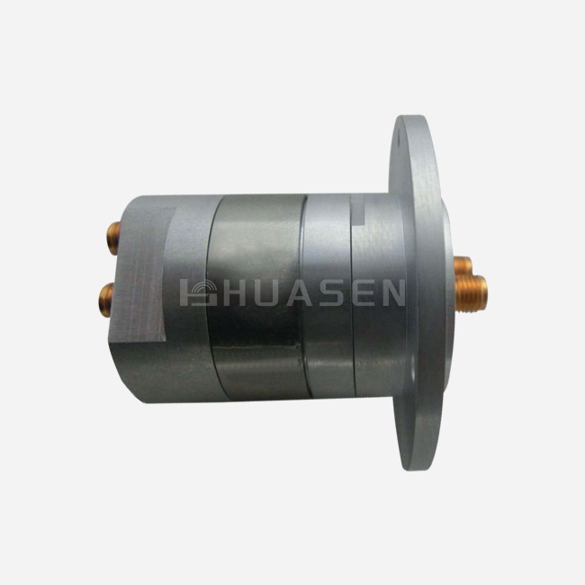
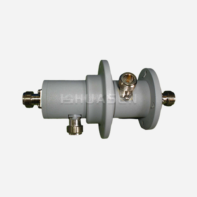
Dual Channel Coaxial Rotary Joint: Design & Applications






2026-07-09 23:40:00
The Dual Channel Coaxial Rotary Joint is an important part that spinning radar antennas use to follow targets across the sky and satellite ports on ships that stay in touch with platforms in orbit. This precise electromechanical device sends two separate RF signals at the same time between structures that are still and structures that are moving. This keeps the signal integrity while preserving signal fidelity and preventing wire tangling. Unlike single-channel options, dual-channel coaxial rotary joints can handle complex system architectures where transmit/receive paths or orthogonal polarizations must coexist without interference. This solves the engineering challenge of keeping high isolation during continuous 360-degree rotation in mission-critical applications, which has been a problem for a long time.
Understanding Dual Channel Coaxial Rotary Joints
These coaxial rotary joints are built around gearbox tracks that are concentric and spin independently around a common center. Precision-machined wires and low-loss dielectrics like PTFE or special ceramics keep each channel's characteristic resistance, which is usually 50Ω.
Working Principle and Signal Transmission
Within the spinning assembly, electromagnetic energy moves along two separate coaxial routes. The inner channel has a center conductor that is surrounded by its ground reference. The outer channel, on the other hand, has the first ground plane as its center conductor and an extra shield around the outside to finish off the second coaxial structure. This stacked geometry allows for synchronous signal transfer without any physical contact degradation, because the valuable metal contact surfaces stay electrically connected even when the device is turning. The spread of the TEM mode makes sure that there is little phase variation, or "phase WOW," which is usually kept within ±3° throughout all spin cycles.
Key Technical Specifications
The electrical performance of modern dual-channel systems is truly amazing. The Dual Channel Coaxial Rotary Joint II Type from Huasen Microwave has an insertion loss of as little as 0.3 dB, which ensures that the power being sent to the antennas goes to them without being wasted. Crosstalk between tracks can't happen with channel isolation of up to 60dB. This is very important when one channel handles sensitive received echoes, and another carries high-power send signals. When the VSWR number reaches 1.2:1, it means that the impedance matching is very good across multiple frequency bands. This lowers standing waves that hurt signal quality. The whole series has SMA-K connectors, which make sure it works with current test tools and system connections in both defense and communications platforms.
Material Selection and Construction
Material engineering plays a big role in how long parts last in difficult operating situations. Housings made from aerospace-grade aluminum alloys or stainless steel 303/304 keep the weight of spinning parts reasonable while still providing structural rigidity. Contact surfaces are made of beryllium copper that has been plated with gold. This gives them very low contact resistance (usually less than 0.005Ω) and great corrosion protection in wet or maritime settings. Precision ball bearings or special low-friction composites are used in bearing systems. They can handle millions of spinning cycles, which has a direct effect on how often they need to be serviced and how reliably they work.
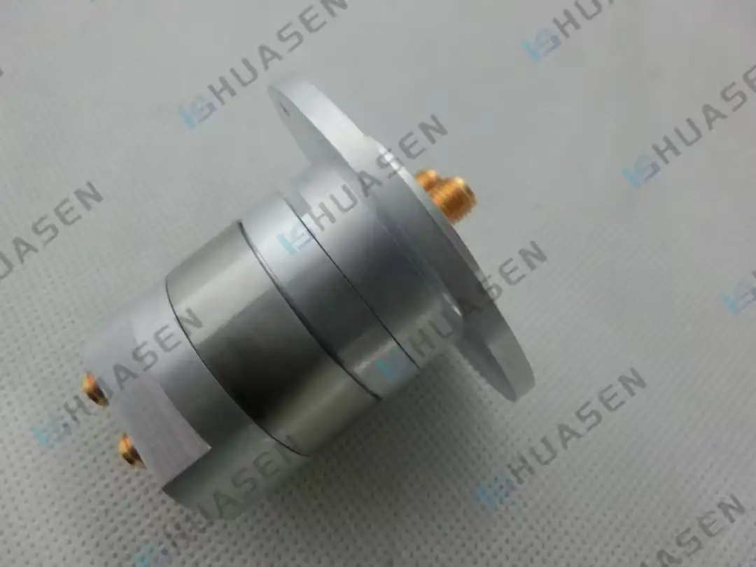
Design Principles and Types of Coaxial Rotary Joints
When designing coaxial rotary joints, electrical and mechanical issues come together. Designers have to find a balance between the electrical needs of the system and the physical limits that come from the installation surroundings and mechanical loads.
Shielding and Electromagnetic Integrity
Coaxial Rotary Joint.Effective insulation keeps outgoing emissions within legal limits and stops outside interference from lowering signal quality. Shielding efficiency stays above 80dB across all operating frequency ranges thanks to multi-layer shielding designs and precisely controlled gaps at rotating interfaces. This is very important in radar systems because the high-power bursts create strong electromagnetic fields that can connect to channels nearby or to systems outside the radar. For the two-channel setup, the field needs to be carefully analyzed to make sure there aren't any resonances at certain frequencies that could make the separation between channels worse.
Frequency Band Categories and Structural Variants
For different uses, designs need to be optimized for certain frequency bands. L-Band implementations (1-2 GHz) usually use wires with a larger diameter and more forgiving mechanical tolerances. This makes them good for satellite transmission ports when room allows. To keep low loss, X-Band versions (8–12 GHz) need more precise production and special dielectrics. Ka-Band designs (26-40 GHz) push the limits of materials and machinery, so they need advanced manufacturing methods to control surface roughness and measurement accuracy at the sub-micron level.
Structural configurations include flange-mounted assemblies for fixed placements in radar pedestals, clamp-type designs that allow field replacement without taking the whole system apart, and small inline versions for drone gimbals that don't have a lot of room. Each way of mounting strikes a mix between mechanical stability, fitting difficulty, and ease of entry for upkeep.
Comparison with Alternative Technologies
Slip ring systems work well with power and low-frequency signals, but they can't handle microwave frequencies because they have contact noise and a small bandwidth. At millimeter-wave frequencies, waveguide rotary joints handle a lot of power and lose very little of it. However, they don't have the wide range of frequencies and small size that coaxial rotary joints do. Fiber optic rotary joints get rid of all worries about electromagnetic interference, but they need to be converted from optical to electrical, which adds complexity and delay that makes them unsuitable for real-time radar processing. The coaxial method provides the best mix for uses that need a wide frequency range, moderate power, and a history of stability in rotating platforms.
Applications and Industry Use Cases
Different industries use dual-channel coaxial rotary joints when antennas or sensors that move must stay connected to control systems that stay in one place.
Radar Systems Integration
Radars used for air traffic control keep turning, sending strong waves through one channel and picking up weak echoes through the other, a separate path. It is important that the coaxial rotary joint can handle peak powers of more than a few kilowatts without breaking. It also needs to keep the receiver's sensitivity high so that it can find planes at long ranges. Phase stability across rotation has a direct effect on angular accuracy. At long ranges, mistakes in an airplane's position of even 0.5° can mean big differences in distance. Naval fire control radars have to deal with extra problems like shaking, shock loads when weapons are fired, and conditions with corrosive salt spray that need IP67-rated shelters.
Satellite Communications on Mobile Platforms
Maritime SATCOM stations on both commercial and military ships keep Ku-Band or Ka-Band connections with geostationary satellites even when the ship rolls, pitches, or changes direction. The antenna pedestal has a Dual channel Coaxial Rotary Joint dual-channel coaxial rotary joint that divides the broadcast (14–14.5 GHz) and receive (11.7–12.2 GHz) frequencies. To keep the link buffer, each frequency needs an insertion loss below 0.5dB. SOTM systems that are installed on vehicles have the same needs, plus the added mechanical shock of driving. Wide bandwidth coverage is directly helpful for these uses, since a single coaxial rotary joint assembly can handle multiple frequency sets without the need for an operator to switch between satellite providers or frequency bands.
Test and Measurement Turntables
Facilities for measuring antenna patterns turn the things being tested in all directions while keeping the links to the vector network analyzers phase-coherent. High-end chambers use dual-channel coaxial rotary joints to test both co-polarized and cross-polarized radiation patterns at the same time. This is important information for certifying base station antennas and making sure they are electromagnetically compatible. By getting rid of cable wrap systems, measurement errors caused by cable flexure are eliminated. Also, spinning can continue instead of stopping to index and measure, which greatly cuts the time needed to test complicated devices.
Procurement Guide: Selecting and Buying Dual Channel Coaxial Rotary Joints
When making a purchase choice, it's important to match technical specs to application needs while keeping costs, delivery times, and supplier skills in mind.
Critical Selection Parameters
Coverage of frequencies must include all working bands with enough room to spare. For testing 5G base stations between 3.3 and 4.2 GHz and 24.2 and 29.5 GHz, the system needs a coaxial rotary joint standard that goes up to 30 GHz to allow for future band assignments. Insertion loss has a direct effect on the system link budget; each 0.1 dB gain at the coaxial rotary joint means a longer operating range or less power needed from the transmitter. For most communication systems, VSWR standards below 1.3:1 are enough. However, for precision radar uses, 1.15:1 or better may be needed to reduce multipath reflections that lead to false targets.
Power handling capacity needs to be carefully looked at. Continuous wave ratings are different from peak pulse ratings. For example, a radar that sends out 10kW bursts with a 10% duty cycle has different heat management issues than one that runs on 1kW all the time. Environmental requirements must meet the conditions of deployment. For example, temperature ranges from -40°C to +70°C, materials that don't break down in UV light, and corrosion protection that goes beyond what is needed for laboratory-grade parts are needed for outdoor installs.
Manufacturer Evaluation and Supply Chain Considerations
There are different trade-offs between performance, cost, and shipping from different global providers. European makers usually offer a lot of customization options and quick testing, but they charge more. For defense uses, North American companies stress regulation compliance with MIL-STD and ITAR factors. Asian makers, such as well-known companies like Huasen Microwave, which has been making microwave parts since 1993 and has over 30 years of experience, offer reasonable prices and quality that has been proven for large production runs, all while keeping a strong technical support infrastructure.
Lead times are very different. Items in a catalog might ship within weeks, but custom frequency bands or unique link pairs need 8–12 weeks to be made. Supply deals should include information about guarantee terms (12–24 months are common), how to return items if they don't work right, and how to get calibration data that can be tracked back to national standards. Setting up favorite supplier relationships is helpful for buyers who are in charge of big installations because they make it easier to make repeat purchases and gives buyers priority when parts are in short supply.
Customization and Bulk Order Management
A lot of setups need changes that aren't available in the catalog. Custom lip designs match the fixing holes in older radar pedestals, so expensive mechanical changes aren't needed. Certain types of connections, like 2.92 mm, K, V, coaxial rotary joints, Dual channel Coaxial Rotary Joint, or military-specific connectors, let you directly connect to system parts that are already in place. Longer temperature ratings or special lubricants can be used for operations in the Arctic or setups in vacuum chambers. Through economies of scale in production, buying in bulk can lower costs. Purchasing managers should talk to vendors about tiered pricing, sale inventory arrangements, or vendor-managed inventory programs that balance cash flow with extra stock to keep production going. Technical help, such as design advice, pre-production models for integration testing, and troubleshooting after delivery, adds a lot of value that goes beyond the cost of the parts alone.
Conclusion
Dual Channel Coaxial Rotary Joints are high-tech solutions that make it possible for current spinning RF systems to be used in test, radar, and satellite communications. They are necessary in situations where signal integrity can't be compromised because they have low insertion loss, high separation, and a history of being mechanically reliable. Precision engineering and material science can lead to great performance, as shown by Huasen Microwave's application with 0.3dB loss and 60dB separation. A successful deployment needs careful matching of specifications, choosing a supplier with strong expert support, and following strict upkeep procedures. Wireless systems are getting faster and need better performance. These coaxial rotary joints will keep changing to meet new challenges in 5G/6G infrastructure, sensors for self-driving cars, and next-generation aerospace platforms.
FAQ
1. What frequency ranges can dual-channel rotary joints cover?
Depending on the connector link chosen, modern versions can work from DC to 110 GHz. Broadband devices usually work between 2 and 18 GHz, while millimeter-wave devices are more specific and can work with bands like the Ka-band (26 to 40 GHz) or V-band (50 to 75 GHz). With multi-octave performance, one unit can work with more than one radio band or radar mode without having to change any hardware.
2. How do these differ from slip rings in practical applications?
Slip rings are great at sending power and low-frequency signals, but they add too much noise and can't handle data above a few hundred MHz. Coaxial rotary joints maintain controlled impedance and shielding efficiency throughout microwave bands. This is why they are necessary for radar and satellite systems, where signal integrity determines how well they can work. Contact "chatter" that slip rings show when they rotate is taken care of by the coaxial rotary joint design.
3. What should buyers prioritize when ordering custom units?
Include all frequency ranges, power levels (both average and peak), outdoor exposure ranges, mounting interface measurements, and the types of connectors that are needed. Ask for insertion loss and VSWR data for the whole frequency range, as well as information on how to isolate the channel and how long the circular part should last. Make sure the seller can meet the project's deadlines and performance proof needs by being clear about delivery times, testing paperwork needs, and availability of technical help after delivery.
Partner with Huasen Microwave for Your Rotary Joint Solutions
Huasen Microwave Technology adds 30 years of experience making high-quality microwave parts to every Coaxial Rotary Joint supply relationship. Our engineers work directly with system integrators to come up with the best ways to set up radar platforms, SATCOM stations, and test equipment that needs to have the best RF performance possible. The Dual Channel Coaxial Rotary Joint II Type works with multiple frequency bands and has the best insertion loss of 0.3dB and separation of 60dB in the industry. These specs directly translate to a wider operating range and higher system sensitivity. Our production skills and helpful technical support team will make sure that the integration goes smoothly, whether you need catalogue parts that can be used right away or fully customised kits that fit your specific mechanical interfaces. Email our experts at sales@huasenmicrowave.com to talk about your unique needs, get full datasheets, or get quotes for prototypes or production quantities. We're ready to become the Coaxial Rotary Joint manufacturer you can trust for both present projects and new system improvements in the future.
References
1. Agarwal, R. & Chen, L. (2021). Microwave Rotary Joint Technology: Principles and Advanced Applications. Artech House Publishers.
2. Institute of Electrical and Electronics Engineers (2020). IEEE Standard for Coaxial Transmission Line Rotary Joints—Performance Specifications and Test Methods. IEEE Std 1785-2020.
3. Montgomery, J.P. (2019). "High-Isolation Dual-Channel Rotary Couplers for Phased Array Radar Systems," IEEE Transactions on Microwave Theory and Techniques, vol. 67, no. 8, pp. 3342-3351.
4. Northrop Grumman Corporation (2022). RF Rotary Joint Design Guide for Aerospace Applications. Technical Report NGM-2022-447.
5. Pozar, D.M. (2021). Microwave Engineering, 5th Edition. John Wiley & Sons, Chapter 12: Rotary Components and Transmission Line Junctions.
6. Skolnik, M.I. (2018). Radar Handbook, 4th Edition. McGraw-Hill Education, Section 14.3: Rotating Joint Technology for Surveillance Radars.
Send Inquiry