Broadband Coaxial Detector Applications in Lab Test Equipment






2026-07-09 23:40:06
Broadband coaxial detectors are very important tools for testing in the lab because they turn RF power into measurable DC voltage outputs over a wide frequency range. Engineers and workers can use these precise parts to check the integrity of signals, adjust equipment, and make sure systems work right in a wide range of situations, such as building 5G networks, testing satellite communications, and making sure radar systems work right. Broadband coaxial detectors make work easier, lower the chance of errors, and help accurately characterize complicated RF systems in places like aerospace and telecommunications research labs by measuring power in real time across bandwidths that usually range from 100 MHz to 18 GHz.
Understanding Broadband Coaxial Detectors and Their Working Principles
Core Technology Behind Broadband Detection
Point-contact diodes or Schottky barrier junctions, along with special microwave matching circuits, are what broadband coaxial detectors are made of. These circuits keep the resistance constant along the coaxial transmission line. This stops signal echoes that would make measurements less accurate. For low-power signals, the diode junction works in the square-law region, making a DC output voltage that is proportional to the RF power that comes in. This conversion mechanism lets lab tools check power levels without getting in the way of the signal path. This kind of tracking is necessary for testing sensitive equipment.
Technical Specifications That Matter
Sensitivity becomes an important factor when judging the performance of a device. Good detectors can pick up small signals with a sensitivity higher than 0.15 mV/μW. This lets you get accurate readings of weak signals that are common in checking receivers and figuring out what an antenna is made of. Frequency flatness—usually kept within ±1 dB per octave—ensures accurate readings across the whole working span without the need for complicated calibration tables. This stability is very helpful when checking wideband parts like filters, amplifiers, and multiplexers, since mistakes that depend on frequency would throw off the results.
Input and Output Interface Compatibility
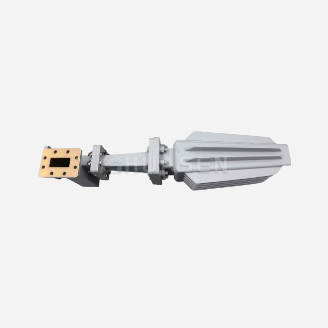
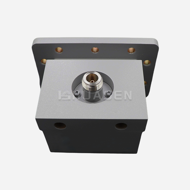
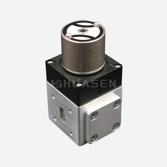
Standardized connector designs on modern broadband coaxial detectors make it easier to add them to test sets that are already in place. Most input ports use SMA-J or N-type female connections that can handle frequencies up to 18 GHz. This means that wires from network analyzers, signal generators, and directional couplers can fit. Most of the time, the output uses BNC-K connections that provide stable DC voltages and can connect straight to oscilloscopes, data acquisition systems, and power meters. Standardizing these connectors makes buying things easier and makes it possible for tools to be used in different lab areas without any problems.
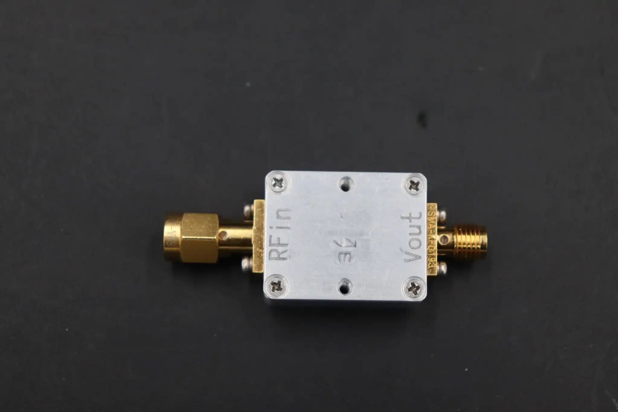
Core Applications of Broadband Coaxial Detectors in Lab Testing
Power Monitoring and Leveling Control
Broadband coaxial detectors are used in RF labs to keep the output power stable in signal producers while frequency sweeps are happening. The detector sends constant input to the automatic level control circuits, which evens out changes in gain across the swept span. This feature is very important for describing frequency-dependent devices because consistent input power has a direct effect on measurement accuracy. Labs that test for telecommunications standard compliance rely on this leveling function to make sure that signals sent stay within certain power limits throughout the working bandwidth.
Component Characterization and Scalar Analysis
Another important use for detectors is network characterization. When used with directional couplers, these detectors make it possible to measure insertion loss and return loss on a scalar level without having to pay for full vector network analysis. The setup for the measurement sends outgoing and reflected signals to different detection channels. This gives amplitude-only S-parameter data that is good for screening the first components. This method speeds up production testing because it doesn't need phase information. This lets makers check for filter passband smoothness, amplifier gain compression, and antenna matching with less complicated equipment.
Pulse Envelope Detection for Radar Applications
Broadband coaxial detectors are used in defense and military labs to look at pulsed RF signals coming from radar emitters and electronic warfare systems. Due to its very short rise time (often measured in nanoseconds), the detector correctly copies pulse modulation patterns seen on oscilloscopes. Engineers check the pulse width, rise and fall times, pulse repeat intervals, and droop features that affect how well the radar can resolve ranges and tell the difference between targets. For this task, you need detectors with a large video bandwidth that can pick up on changing features without distorting them. These are the features that set professional-grade detectors apart from other types.
How to Choose the Best Broadband Coaxial Detector for Your Lab Needs?
Defining Your Measurement Requirements
Understanding your test cases well is the first step in choosing the right monitoring technology. When labs do low-level tests on receiver parts, they need the highest levels of sensitivity. When checking transmitters, they need the ability to handle more power. All operating bands must be covered by the frequency range. A single broadband coaxial detector that works from 0.1 GHz to 18 GHz removes the need for multiple instruments for sub-6 GHz, C-band, X-band, and Ku-band tasks. Overload safety is very important when testing high-power amplifiers. Detectors rated for input power below 20 mW keep the sensitive diode junction from getting damaged by mistake during setup.
Evaluating Key Performance Indicators
Besides looking at basic specs, buying managers should also check the dynamic range, which is the ratio of the highest and lowest amounts of power that can be detected. A wider dynamic range means that there is less need for attenuators or amplifiers in the signal line. This makes test setups easier and increases the accuracy of measurements. Temperature stability specs show how the sensitivity of the detector changes over the normal temperature range found in labs. Detectors that work the same from 0°C to 50°C allow year-round use in places that don't have strict temperature control.
Supplier Considerations for Long-Term Partnerships
Established companies like Huasen Microwave Technology have been making RF components for decades and have worked in the aircraft, radar, and telecommunications industries since 1993. Their technical support helps with integration problems that are specific to an application, adapting connectors, and making sure that the calibration methods are right for your instruments. When looking at different sources, make sure to check if they have quality control certifications, warranties that cover both parts and labor, and the ability to provide calibration data that can be tracked back to national standards. Organizations that need to outfit multiple labs or support large-scale production testing can benefit from bulk buy deals that offer discounts based on volume and faster delivery times.
Best Practices for Usage, Calibration, and Maintenance in Labs
Installation and Initial Setup Procedures
To avoid mechanical damage, the right way to put something together starts with making sure the connectors work together and that the force requirements are met. To get consistent electrical performance from SMA connectors, torque values of 7 to 10 inch-pounds must be applied with measured tools. This is to avoid putting too much stress on the center pin. As a standard, measure the broadband coaxial detector's no-signal output voltage after it has been physically installed. If it changes during future tests, it means that the potential DC offset has drifted and needs to be adjusted for calibration.
Calibration Intervals and Verification Methods
How often calibration is done depends on how often the application is used and how important it is. Labs that take readings that have to be traced back to government standards should use known reference sources, such as regulated power meters and RF signal generators, to check the accuracy of detectors once a year. During the calibration process, different power levels are applied across the detector's working bandwidth, and the output voltages are compared to what the detector's sensitivity standard says they should be. Putting calibration data in maintenance logs makes it possible to track down problems and find long-term drift trends that show when a part is getting old.
Troubleshooting Common Operational Issues
If detectors give you strange readings, you should check the RF input line for broken wires, corroded connections, or contamination at the points where the two interfaces meet. Clean the threads on the connectors with rubbing alcohol, and use a magnifying glass to look for distortion in the center pins. Make sure that the DC output wiring doesn't get messed up by electromagnetic fields by moving it away from strong RF lines. Broadband coaxial detectors that are exposed to input power that is higher than their highest rate will suddenly lose their sensitivity. This damage can't be fixed, so the unit must be replaced instead of being tried to be fixed.
Future Trends and Innovations in Broadband Coaxial Detector Technology
Enhanced Frequency Coverage and Millimeter-Wave Extension
As of now, the main focus of research work is on expanding detector bandwidths into millimeter-wave frequencies above 40 GHz to meet the needs of new 5G and 6G test standards. These next-generation detectors use advanced diode designs with lower junction capacitance, which lets them work at frequencies where regular Schottky diodes lose their sensitivity. Labs getting ready to test millimeter-wave components should keep an eye on provider roadmaps for detectors that cover the 24 GHz, 28 GHz, and 39 GHz bands that will be used for 5G new radio operations.
Digital Integration and Smart Calibration Features
New types of broadband coaxial detectors have microcontrollers built in that store calibration factors, fix temperature drift automatically, and talk to each other through digital ports like Ethernet or USB. By using internal temperature monitors and frequency-dependent calibration tables to make changes in real time, these smart detectors lower the uncertainty of measurements. Digital output gets rid of the mistakes that come with measuring voltage analogly, and remote tracking lets automated test systems work without being watched for long periods of time.
Market Dynamics Shaping Procurement Strategies
Companies are making modular broadband coaxial detector-based detectors that work with standard instrument frames and software-defined measurement platforms because more people want test options that are all in one. The total cost of ownership should be looked at by procurement professionals. This includes things like software licensing, firmware update policies, and the availability of measurement methods that are special to the application. When test labs need more space for tests, scalable designs that let channels grow can help without having to update the whole system.
Conclusion
Broadband coaxial detectors are still necessary for accurate RF power measurements in labs that help build telecoms infrastructure, test radar systems, and make sure aircraft parts are safe to use. Knowing how detectors work, what they need to be used for, and how well they should perform helps you make smart purchases that match the instruments' skills with your test goals. Huasen Microwave's detectors are perfect examples of the precise engineering and application-focused design needed to meet the strict needs of laboratories working with frequencies from 0.1 GHz to 18 GHz. Strategic relationships with suppliers, regular testing procedures, and keeping an eye on new technology trends all help to make sure that measurement capabilities change along with new wireless communication standards and more complicated RF system designs.
FAQ
1. What factors most significantly affect detector measurement accuracy?
The three main problems with precision are frequency flatness across the working bandwidth, input VSWR that causes signal reflections, and temperature-induced sensitivity drift. These causes of error are kept to a minimum by detectors with VSWR below 1.5:1 and ±1 dB flatness per octave. This lets you get accurate readings without having to use a lot of correction factors.
2. How often should laboratory detectors undergo calibration?
Most general-purpose lab uses can be met with annual testing times. Facilities that help with testing for legal compliance or quality control in production should set up calibration plans every six months. Extreme temperatures or exposure to mechanical shocks in the environment may mean that proof needs to happen more often.
3. Can broadband detectors measure both continuous and pulsed signals?
Even though the result is different, the answer is yes. Signals that are continuous waves make DC voltages that don't change, while signals that are pulsed make outputs that change over time and copy the pulse shape. For pulse measurements, oscilloscopes are used to record the video output from the detector. For CW measurements, DC voltmeters or data capture tools are used to take samples at slower rates.
Partner with a Proven Broadband Coaxial Detector Manufacturer
Huasen Microwave Technology makes Broadband Coaxial Detectors that are carefully built to work in tough lab test settings. Our devices have outstanding sensitivity of more than 0.15 mV/μW across 0.1 to 18 GHz bandwidths and the best frequency flatness in the business at ±1 dB per octave. Point-contact diode technology and custom matching circuits make sure that measurements are stable, which is important for radar, telecommunications, and aircraft uses. As a reliable provider with 30 years of experience making high-quality RF components, we offer full technical support, reasonable pricing for large orders, and dependable delivery plans that meet project deadlines. Email our engineering team at sales@huasenmicrowave.com to talk about your unique measurement needs and find out how our detector solutions can help your lab work better.
References
1. Pozar, David M. Microwave Engineering, 4th Edition. Wiley, 2011.
2. Agilent Technologies. Fundamentals of RF and Microwave Power Measurements. Application Note 64-1A, 2001.
3. IEEE Standard 1138-2009. IEEE Standard for Testing and Performance for Optical Ground Wire (OPGW) for Use on Electric Utility Power Lines.
4. Keysight Technologies. Spectrum and Signal Analysis Application Note, 2020.
5. Bhat, B. and Koul, S.K. Stripline-like Transmission Lines for Microwave Integrated Circuits. New Age International Publishers, 1989.
6. Rohde & Schwarz. Power Meter Selection and Calibration Guide for Modern RF Test Systems. Technical White Paper, 2019.
Send Inquiry