Space-Constrained Satellite Design Using Planar Helical Antenna






2026-07-09 23:40:03
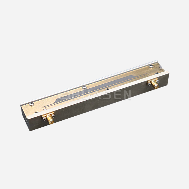
These days, satellite systems need small, high-performance parts that do a lot of work while taking up very little space. This main problem is solved by the Planar Helical Antenna, which changes standard three-dimensional spiral structures into slim, low-profile ones. This change in design makes it possible for satellite engineers to add ultra-wideband signal reception across the frequency range of 0.2 to 18 GHz without having to cut back on ship volume. Its circular polarization, which is set by the direction of the helical winding, and VSWR values usually less than 2.5, make sure that the signal stays intact in a wide range of mission types, from electronic espionage to multiband communication systems in CubeSats and microsatellites.
Understanding Planar Helical Antennas in Satellite Applications
There are strict rules about how satellite systems can work, and every cubic centimeter counts. Traditional helical antennas work well, but they stick out from the sides of spacecraft, which creates atmospheric drag during launch and makes it harder to integrate them into satellite buses that are already very crowded.
The Structural Advantage of Planar Design
A new way of thinking about antenna building is the planar helical radiation surface. In contrast to most structures that stick out, this one fits almost flush against mounting surfaces. To do this, engineers use PCB photolithography methods on dielectric surfaces to make conductive spiral arms with designs that are often Archimedean or equiangular. Behind the radiating element is a space filled with material that absorbs radiation. This does two things: it keeps backside radiation from interfering with electronics on board to a minimum and sends energy straight into space.
This way of building directly solves the size problems that nanosatellite designs have. When your aircraft is 10x10x30 centimeters, like many 3U CubeSats are, choosing the right antenna is very important. While keeping the traveling-wave properties that make for wide bandwidth coverage, the flat method makes good use of vertical space.
Circular Polarization Benefits for Space Links
Signals in satellite communications often get weaker because of Faraday rotation in the ionosphere and multipath echoes off the surfaces of planets. As satellites move or tumble, they lose linear polarization in ways that depend on their direction. These problems can't happen with circular polarization because it's symmetrical around its spin.
Based on the direction of the winding, the helical shape automatically creates either right-hand or left-hand circular polarization. This trait is very useful for data downlinks from satellites whose attitude changes quickly and without warning. Ground stations get the same signal strength no matter which way the satellite is facing. This keeps the link gaps that linear antennas can't ensure. The axial ratio performance, which measures the purity of the polarization, stays the same across the operating bandwidth. This makes sure that the system works reliably during important mission stages.
Real-World Deployment Scenarios
Microsatellite groups used to observe Earth depend more and more on small antenna options. A new microsatellite program needed to be able to receive signals across the ultra-wideband range, from S-band to Ku-band, in order to gather electronic information. In the past, options would have needed a lot of separate antennas, and each one would have taken up valuable payload space. The setup Planar Helical Antenna design worked across the full 0.2–18 GHz range, with gain levels between -5 and 5 dB. This was good enough for receiving antenna feed systems where signal aggregation is more important than high directivity.
Maritime transmission satellites (planar helical antennas) have to deal with extra problems like rust from salt water and changes in temperature between stages of sun and eclipse. The sealed hole in the planar design covers the inside surfaces, and the strong substrate can handle temperature changes from -40°C to +85°C without delamination or performance shift.
Comparing Planar Helical Antennas with Alternative Antenna Solutions
To choose the best antenna technology, you need to know what the pros and cons of each design are. Each approach has its own benefits for the design of satellite systems.
Microstrip Patch Versus Planar Helical Performance
Microstrip patch antennas are the most common type used in business satellite applications because they are easy to make and don't cost much. They work great in narrowband situations where a single frequency is enough. Patch antennas, on the other hand, have trouble with their limited bandwidth—usually only 3–5% of the total bandwidth before impedance matching breaks down.
The planar helical antenna design provides octave-spanning or multi-octave bandwidth, which can cover frequency ranges that would need more than one patch element stacked on top of each other. A patch might only work with the GPS L1 band, but a planar helical antenna design can receive GPS L1, L2, and L5 at the same time, plus Galileo and GLONASS frequencies. This merging cuts down on the number of parts, makes feed networks easier to use, and lowers the total mass of the system.
Different tools make circular polarization in very different ways. To get circular polarization with patch antennas, you need dual-feed networks or corner truncations, which cause insertion losses and axial ratio degradation. As a result of its spiral shape, the design automatically creates circular polarization, keeping the axial ratio below 3 dB over a wider range of angles.
Monopole and Dipole Limitations in Space Environments
Monopole and dipole antennas can send signals in all directions, which is useful for satellites that need circular or hemispherical radiation patterns. However, because they are linearly polarized, they can fade depending on the direction they are facing. The received signal strength changes a lot when a satellite rotates, and it could drop below the receiver's sensitivity levels during important data transfer windows.
In addition, these devices need ground planes or counterpoises, which take up space in the building. The Planar Helical Antenna hollow works as a single ground structure, so there's no need for separate fixing. When it comes to mechanical integration, this feature of being self-contained makes designing attaching brackets easier and cuts down on the work that needs to be done during satellite assembly.
Spiral Antenna Comparison and Niche Applications
Spiral antennas and planar helical antenna designs both work as frequency-independent structures and have similar bandwidth properties. The main difference is in the form of the radiation pattern and how the gain is distributed. Spirals make beamwidths that are wider but have lower gain, which is good for finding directions but not so good for point-to-point links that need to optimize gain.
Planar helical antenna designs are great for electronic espionage receiving antennas (helical antennas) that need to collect signals over wide bandwidths while also being moderately directed. This is because they strike a good balance between pattern coverage and gain. The -5 to 5 dB gain range works with a number of different system designs, from low-gain wideband surveillance sensors to fairly directive feed elements for reflector systems.
Design Principles and Optimization Techniques for Planar Helical Antennas
When designing high-performance antennas for use in space, it's important to pay close attention to electromagnetic concepts and the facts of manufacturing. The planar helical antenna shape gives you a lot of ways to improve performance, so you can make it fit your mission needs.
Radiation Pattern Engineering
Choosing the right physical parameters is the first step in getting the radiation properties you want. The working frequency range is based on the length of the spiral arm; longer lines can handle lower frequencies. Arm width and spacing affect input resistance and bandwidth, so electromagnetic modeling tools are needed to make sure that everything is balanced.
Engineers have to think about the beamwidth needs that come up in contact situations. Wide-angle coverage works best for omnidirectional data links to spread-out ground stations, while smaller beams focus energy on certain orbital angles. The depth of the backing hole changes the front-to-back ratio. This stops radiation from reaching the inside of the spaceship and damaging its electronics or propulsion systems.
Using the finite element method or the method of moments analysis to validate simulation software lets you guess how it will work before making a prototype. These computer programs can model substrate dielectric constants, circuit losses, and edge effects that closed-form equations can't fully describe. Validated models allow for quick design feedback, which cuts development times from months to weeks.
Substrate Material Selection and Thermal Management
The choice of dielectric material has a big impact on both electrical performance and longevity in harsh environments. Rogers RO4003C and other related PTFE-based laminates have stable dielectric constants over a wide range of temperatures that are common in low-Earth orbit. Their low-loss vector keeps the signal's purity by lowering the amount of insertion loss in the feed network.
When satellites move from being in the sun to being in the Earth's shade, a process called thermal cycling can be very difficult. Substrates have to stay the same size and shape through hundreds of rounds of very high and very low temperatures without bending or peeling. Matching the coefficients of thermal expansion between the wire and the substrate stops stress buildup that causes trace cracks.
The material used for the hollow absorber needs special care. It has to be able to absorb waves in a wide range of frequencies, from 0.2 GHz to 18 GHz, and it has to be able to withstand vacuum outgassing conditions set by NASA. These features are made possible by polyurethane foam that has been mixed with carbon particles. This foam separates the front and back antenna sections by 20+ dB.
Customization Processes for Mission-Specific Requirements
Off-the-shelf parts are rarely accepted by satellite systems without being changed. How frequency bands are used depends on the mission license, the orbital slot, and the regulatory authority. Planar helical antenna shapes can be customized to fit these special needs through a number of adjustment methods.
Helical Antenna: The working frequency range changes in a proportional way when the whole spiral shape is scaled. The center frequency is cut in half when all lengths are doubled. This is a simple relationship that makes adaptation easier. You can fine-tune the bandwidth and axial ratio performance for uneven frequency plans by changing the number of arms or the thickness of the windings.
To reverse the polarization sense, you have to image the spiral pattern backwards and forwards, switching from right-hand circular to left-hand circular polarization. This change is very important when satellite groups use polarization variety to double channel capacity within the same frequency allocations. It only takes minutes to make in CAD software.
Conclusion
Planar helical antennas get around the basic space problems that current satellite makers face by being small and covering an extremely wide range of frequencies, from 0.2 GHz to 18 GHz. Their circular polarization makes communication links strong even if the spacecraft's direction changes, and cavity-backed designs keep interference with onboard systems to a minimum. Planar helical antenna designs offer better bandwidth, polarization purity, and ease of fitting compared to other options such as microstrip patches or monopoles. Strategies for buying things that focus on supplier certification, expert help, and working together for a long time improve both the performance of parts and the control of program risks. As the number of satellite groups grows and additive manufacturing improves, planar helical antenna technology will keep moving toward reconfigurable, multi-band designs that make operations more flexible while keeping costs low.
FAQ
1. What frequency ranges do planar helical antennas cover effectively?
It has been shown that these antennas work well across ultra-wideband frequency licenses, from 0.2 GHz to 18 GHz in single designs. This range includes many different satellite transmission bands, such as VHF, UHF, L, S, C, X, and Ku bands. The ability to work across a wide frequency range comes from the way traveling waves work, where the length of an electrical signal stays equal to its wavelength across frequencies, easily meeting the impedance. Through geometric scaling, mission-specific solutions improve speed within parts of this range.
2. How does circular polarization benefit satellite communication links?
Linearly polarized systems are prone to orientation-dependent fading, but circularly polarized systems are not affected by this. Even when satellites tilt or spin, circularly polarized signals stay connected to base antennas the same way they always have. This trait is very important for small satellites that don't have active position control. In addition, circular polarization lessens the effects of Faraday spin in the ionosphere and multipath interference from surface reflections. This increases signal-to-noise ratios by 3–6 dB in difficult propagation settings.
3. Can planar helical antennas withstand launch vibration and space environments?
When made correctly with space-qualified materials and attachment methods, these antennas can withstand launch loads of more than 14 G and keep working even when the temperature changes from -40°C to +85°C. The flat design gets rid of weak, visible parts that could be damaged by vibrations. Atomic oxygen corrosion in low-Earth orbit is kept out of the inside surfaces by hermetically sealed holes. Meeting the standards for MIL-STD-810 environmental tests and NASA outgassing guarantees long-term dependability during multi-year missions.
4. What customization options exist for mission-specific requirements?
Planar helical antenna designs are customized by manufacturers based on a number of factors, such as frequency band optimization, polarization sense selection, gain profile change, and mechanical interface specs. The type of substrate material used depends on how the heat needs to be managed, and the type of connection used depends on the spacecraft's RF design. The cavity absorber's makeup changes to meet the needs for both weight and insulation. Custom designs usually take between 8 and 12 weeks to make, but this depends on how complicated they are. You can test small amounts of the design before committing to larger sales.
Partner with Huasen Microwave for Your Satellite Antenna Needs
For over 30 years, Huasen Microwave has been a leader in RF and microwave engineering. They are now working on developing space-qualified antennas, blending their deep scientific knowledge with reliable manufacturing skills. As a well-known provider of Planar Helical Antennas, we help satellite projects from the initial design advice all the way through production, delivery, and support after launch. Our engineering team works closely with system developers to make sure that the antenna works best for each mission's specific requirements. This makes sure that it fits perfectly into your spacecraft's platform. We offer parts that meet the strict reliability needs of space uses. Our products are certified by organisations like ISO 9001 and follow international quality standards. Email our expert sales team at sales@huasenmicrowave.com to talk about your project needs and get specific information for your satellite communication system.
References
1. Balanis, Constantine A. (2016). "Antenna Theory: Analysis and Design, Fourth Edition." John Wiley & Sons, Hoboken, New Jersey.
2. Stutzman, Warren L. and Thiele, Gary A. (2012). "Antenna Theory and Design, Third Edition." John Wiley & Sons, New York.
3. Volakis, John L. (2007). "Antenna Engineering Handbook, Fourth Edition." McGraw-Hill Professional, New York.
4. Makarov, Sergey N. (2002). "Antenna and EM Modeling with MATLAB." John Wiley & Sons, New York.
5. Kraus, John D. and Marhefka, Ronald J. (2002). "Antennas for All Applications, Third Edition." McGraw-Hill Higher Education, Boston.
6. Huang, Yi and Boyle, Kevin (2008). "Antennas: From Theory to Practice." John Wiley & Sons, Chichester, United Kingdom.
Send Inquiry