Materials Used in Waveguide Matching Load






2026-05-29 22:00:35
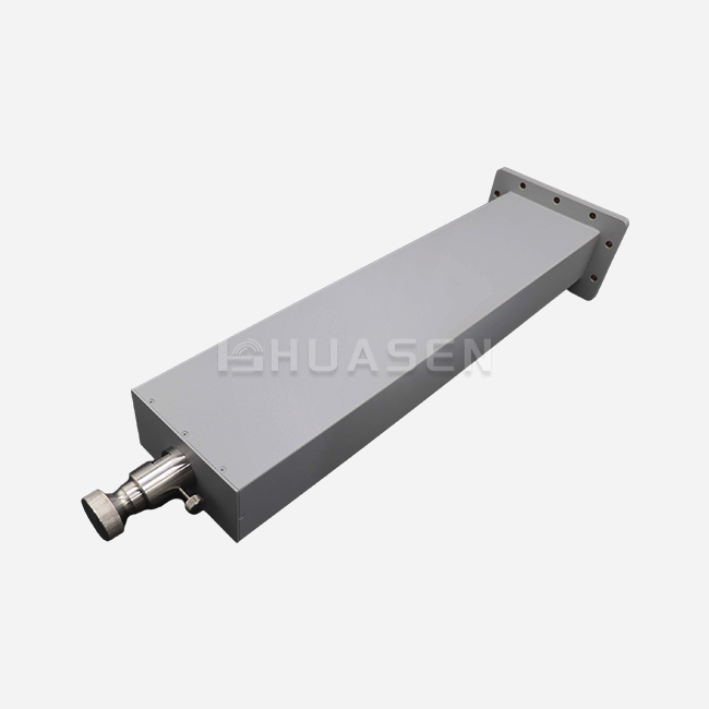
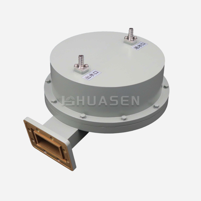
RF and microwave termination devices, waveguide matching loads, absorb electromagnetic energy with little signal reflection to safeguard equipment and signal integrity. Electrical performance, power handling capacity, thermal stability, and endurance depend on these components' materials. To fulfil 5G infrastructure, satellite communications, radar systems, and laboratory instrumentation demands, modern matching loads use absorptive media, dielectrics, metal housings, and protective coatings. Understanding the material science behind these devices helps procurement professionals and system engineers specify components that operate reliably from 0.32 GHz to 330 GHz in harsh environmental conditions and high continuous wave power levels.
Understanding Waveguide Matching Loads and Their Material Requirements
Microwave engineers and procurement professionals wonder what makes one termination better. The answer is material engineering.
The Fundamental Role of Absorptive Materials
Waveguide terminations absorb electromagnetic energy to generate heat. Bulk absorptive materials resist vibration and dissipate energy uniformly, unlike sheet-type resistive films that are mechanically stressed. Core absorbers include silicon carbide, loaded epoxies, and ferrite composites. These materials must have low reflection coefficients and uniform dielectric characteristics over the operational bandwidth. Well-designed molecular structures interact with electric and magnetic field components to transform wave energy into thermal energy without causing standing waves that might harm upstream amplifiers or affect measurement precision.
Material Properties Governing Electrical Performance
The industrial standard is voltage standing wave ratio (VSWR) ≤ 1.10:1, which requires absorptive materials with accurate permittivity and permeability. Gradual material composition changes enable impedance matching and return loss over 26 dB. Advanced manufacturers solve thin-film failure modes using bulk absorption. Sheet-type structures delaminate or crack during shipping and installation due to heat cycling or mechanical stress. Solid bulk materials exceed MIL-STD-202 vibration parameters and ISO environmental standards for aerospace and defence applications, and preserve structural integrity and electrical properties.
Thermal Management Requirements
High-power base station testing and radar calibration create heat in small termination volumes. Material selection must include thermal conductivity, specific heat capacity, and expansion coefficients. Aluminium oxide ceramics assist absorptive materials mechanically and transmit heat well. Copper and aluminium heat sinks transmit heat from the absorbent core. Preventing thermal stress fractures during power cycling demands careful engineering at material junctions. Impedance discontinuities caused by temperature gradients can lower VSWR performance, especially in wideband systems with several frequency bands.

Common Materials Used in Waveguide Matching Loads and Their Properties
Material science has transformed termination design in the last 30 years. We create components based on extensive field deployments and laboratory validation.
Ferrite Composites for Magnetic Field Absorption
Ferrite materials absorb electromagnetic wave magnetic field components well due to resonance losses and domain wall motion. Manganese-zinc and nickel-zinc ferrites absorb frequency dependently. These ceramic compounds are suited for L- and S-band applications due to their high permeability at lower microwave frequencies. The material's Curie temperature determines its highest functioning limit, usually 125°C to 300°C, depending on composition. Tapered ferrite wedges reduce reflections across octave bandwidths by introducing progressive impedance changes. Cost matters in high-volume production since pure ferrite materials cost more than resistive ones.
Silicon Carbide and Resistive Absorbers
Silicon carbide has excellent heat conductivity and controlled electrical resistance. A semiconductor material absorbs energy through resistive heating and effectively transfers heat to mounting flanges and cooling fins. To optimise absorption for certain frequencies and power levels, engineers can modify dopant concentrations. From cryogenic temperatures to 600°C, the material remains robust, sustaining harsh situations. Loaded epoxy formulations contain conductive particles in polymer matrices—allowing design flexibility and cheaper manufacturing costs. Complex waveguide-shaped composite materials may be manufactured to ensure electromagnetic field interaction across the absorption area.
Metal Housings and Thermal Interface Materials
In the case of aluminium 6061-T6 and brass alloys, most waveguide terminations are framed, including the Waveguide Matching Load. Metallic materials offer electromagnetic shielding, mechanical mounting points, and heat dissipation. Anodising, plating, and chromate conversion coatings prevent corrosion in marine and outdoor systems. Precision-machined waveguide flanges fit FDP, FBP, and FUGP interfaces. Absorptive components and metal housings use thermal interface materials to prevent air gaps that hinder heat transmission. Graphite-based compounds and phase-change materials sustain contact pressure throughout thermal expansion cycles, saving thousands of operating hours of performance deterioration.
Dielectric Supports and Encapsulants
Low-loss mechanical support and thermal control are provided by alumina and boron nitride ceramics. Absorptive elements can work without parasitic reflections from support structures in these materials due to low electromagnetic interaction. Encapsulating chemicals prevents moisture and handling damage to interior components. Silicone-based compositions cope with material thermal expansion at severe temperatures. Vibration settings like aircraft and drone-mounted communication systems, where shock loads can surpass 40 G, require proper support structure material selection.
Waveguide Matching Load Design Principles Influenced by Material Choice
Material qualities determine terminal design limits and opportunities. Successful products balance competing needs through clever material choices, according to 30 years of manufacturing expertise.
Electromagnetic Optimisation Through Graded Absorption
Impedance matching necessitates incremental air-filled waveguides to totally absorptive sections. Material engineers use geometric tapering and compositional gradients. A termination for X-band (8.2-12.4 GHz) may have three absorption zones with increasing dielectric constants. This stepwise method reduces reflection coefficients while being compact. Our bulk absorption materials provide accurate transition control, enabling wideband designs for entire waveguide bandwidths and narrowband enhancements for specialised communication channels. Short-length designs serve space-constrained applications where every millimetre counts by sacrificing bandwidth homogeneity.
Thermal Design Integration
High-power termination material selection is based on power dissipation. In an enclosed rack, a 20-watt continuous wave device must transmit heat by conduction, convection, and radiation. Material thermal conductivities determine temperature differences between hot absorptive zones and mounting surfaces. Finite element heat analysis guides metal alloy, ceramic thickness, and fin shape choices. Forced air or liquid cooling is needed at greater dissipation rates; however, natural convection cooling works for power levels below 5 watts. Our monolithic bulk architecture provides better thermal channels than stacked assemblies with interface resistances.
Environmental Durability Considerations
Military and aerospace requirements include salt fog, humidity, and altitude tolerance from -55°C to +125°C. Material compatibility testing ensures thermal cycling won't cause mechanical problems due to thermal expansion incompatibilities. Seals and gaskets prevent moisture from affecting dielectric characteristics or corroding. Metal surface coatings must endure installation abrasion without affecting electrical conductivity at flange contacts. The extensive material certification procedure assures products retain the required VSWR and power handling for over 100,000 operating hours in controlled conditions.
Comparative Analysis: Waveguide Matching Loads vs Other Load Types Based on Materials
System designers examine load technologies to find the best ones for their needs. These component types differ mainly in material composition.
Waveguide Terminations Versus Coaxial Dummy Loads
Resistance films on ceramic substrates or wire-wound resistors in cylindrical housings are used in coaxial dummy loads, providing a matching load. These structures handle milliwatts to kilowatts, depending on size and cooling. Waveguide implementations use bulk absorptive material in three-dimensional volumes for higher power density and reduced VSWR over wider bandwidths. Due to precise application performance, waveguide designs have greater material costs per unit volume. In frequencies below 18 GHz, connection availability and system compatibility favour coaxial transmission. Waveguide technologies outperform coaxial solutions above 26 GHz due to lower insertion loss and greater power management.
Ferrite Isolator Loads Versus Resistive Terminations
Ferrite circulators and isolators absorb reverse-travelling signals with matching loads on isolated ports. Compact size, broadband performance, and magnetic field operation are difficult for these terminations. Material selection prioritises ferrite compositions suitable for permanent magnet assemblies to avoid demagnetisation and maintain absorption throughout temperatures. Without magnetic interaction limitations, standard resistive terminations maximise power handling and the lowest VSWR. Ferrite-based systems cost more owing to sophisticated material processing and stringent production tolerances.
Fixed Versus Adjustable Sliding Loads
Fixed terminations use frequency-optimised fixed bulk absorbers. Sliding load arrangements use precise mechanical mechanisms to move absorptive materials and change the reflection phase for calibration. Low-friction bearings, sturdy guide rails, and electrically continuous contact materials are needed for moving parts. Material wear resistance is crucial in laboratory instruments with thousands of adjustment cycles. The mechanical complexity and material requirements triple manufacturing costs compared to fixed designs; hence, they are primarily used in metrology applications where phase-variable references are necessary.
Procurement Considerations: Selecting the Right Material for Your Waveguide Matching Load
Material selections impact the total cost of ownership and application compatibility; thus, informed purchase decisions are needed. Thousands of clients have used our standard help.
Matching Materials to Operating Environments
To resist salt spray, maritime communication systems need corrosion-resistant coatings and sealed buildings. Desert satellite ground stations need materials that can withstand severe temperatures and UV radiation. Laboratory reference standards value dimensional stability and calibration retention over ruggedness. Specifying environmental criteria during procurement ensures material selection matches deployment circumstances. Products that pass MIL-STD-810 environmental testing reduce risk in important applications by demonstrating performance under various stress conditions.
Balancing Performance and Budget Constraints
Premium bulk absorptive materials facilitate demanding measurement applications and safeguard sensitive solid-state amplifiers with VSWR < 1.05:1 over broad waveguide bandwidths. Standard formulas meet transmitter testing and termination demands with a 1.10:1 VSWR at a cheaper cost. For dedicated channel applications, narrowband optimisations focus material investments in certain frequency bands, lowering unit costs. When standardising flange types and power ratings across system topologies, volume purchase sometimes yields advantageous prices. Customised material formulations take 8-12 weeks longer than catalogue items, requiring project scheduling.
Evaluating Manufacturer Material Expertise
Commodity vendors differ from engineering partners in material science, particularly in terms of matching loads. Manufacturers with in-house R&D labs provide absorptive compositions for millimetre-wave 5G channels. Material synthesis, component production, and final testing are vertically integrated for consistency and traceability. AS9100 aerospace standards and ISO 9001 quality management certifications evaluate process controls. Application-specific material suggestions, sample assessment programmes, and complete electrical and thermal performance test data should be part of technical support. Established vendors maintain material requirements throughout production batches, ensuring replacement units match original equipment years later.
Conclusion
VSWR, power handling, thermal stability, and operational dependability depend on material selection for waveguide matching load performance. Bulk absorptive formulations of silicon carbide, ferrite composites, and specific dielectrics withstand vibration better than sheet-type designs. Metal housings filter electromagnetic waves and control thermal energy, while protective coatings withstand harsh circumstances. Understanding material qualities helps procurement experts define terminations that match application requirements and optimise TCO. High-frequency, high-power applications where material performance directly impacts system success show the advantages of waveguide matching load implementations over coaxial ones. Partnering with manufacturers who rigorously qualify materials and customise capabilities guarantees your important RF infrastructure runs dependably over its intended lifespan.
FAQ
1. What absorptive materials work best for millimetre-wave terminations?
Fine-grain silicon carbide and specially loaded ceramics perform well at millimetre-wave frequencies exceeding 30 GHz because of their controlled dielectric characteristics. At short wavelengths like WR-28, WR-15, and smaller waveguide bands, these materials absorb radiation effectively. Bulk formulations eliminate the dimensional tolerance issues that afflict thin-film resistive methods at such small scales and work consistently.
2. How do material choices affect power handling limits?
How effectively RF energy leaves the contact area depends on thermal conductivity. Poor heat dissipation causes hot patches that can harm materials or electrical components. Silicon carbide's high thermal conductivity (120 W/m·K) allows for larger power ratings in small volumes than loaded epoxies (1-5 W/m·K). Material selection and cooling processes determine safe continuous wave and peak power limitations.
3. Can standard materials withstand space environment radiation?
Ionising radiation degrades polymer-based encapsulants and loaded epoxies in orbit. Space-qualified terminations use radiation-hardened ceramics and metals to preserve characteristics during missions. Alumina ceramics and pure metal absorbers are favoured over organic substances that undergo polymer chain scission and outgas in a vacuum due to total ionising dose requirements.
4. What material properties ensure long-term VSWR stability?
Dimensional stability and resistance to moisture absorption preserve impedance matching over years of operation. Ceramics and metals retain their dimensions during temperature cycling, whereas hygroscopic materials grow in humidity, changing electrical properties. Accelerated life testing must examine material ageing under thermal stress to ensure VSWR standards throughout the guarantee term.
Partner with Huasen Microwave for Superior Waveguide Termination Solutions.
Manufacturing companies with material science competence and 30 years of manufacturing experience are trusted Waveguide Matching Load providers for engineering teams. Huasen Microwave Technology uses innovative bulk absorption materials to prevent sheet-type construction vibration susceptibility, ensuring constant performance throughout long operational lifetimes. Our product offering covers 0.32 GHz to 330 GHz with power handling from 0.3 W to 20 W continuous wave, conventional FDP, FBP, and FUGP flanges, and customisation for particular system requirements.
Whether your application demands compact short-size configurations for narrowband channels, adjustable sliding loads for precision calibration, or dual-ridge terminations compatible with specialised waveguide geometries, our material engineering team can specify optimal solutions. Technical performance, environmental resilience, certification requirements, and financial limits are considered in purchase decisions. Contact our applications engineering team at sales@huasenmicrowave.com to discuss your needs. As an established Waveguide Matching Load manufacturer, we provide technical documentation, sample evaluation programs, and responsive support throughout your product lifecycle—ensuring your RF systems achieve their performance potential through properly specified termination components.
References
1. Pozar, David M. Microwave Engineering, 4th Edition. John Wiley & Sons, 2011.
2. Saad, Theodore S. Microwave Engineers' Handbook, Volume 2: Microwave Components. Artech House, 1971.
3. Baden Fuller, A.J. Ferrites at Microwave Frequencies. Peter Peregrinus Ltd, 1987.
4. Matthaei, George L., Leo Young, and E.M.T. Jones. Microwave Filters, Impedance-Matching Networks, and Coupling Structures. Artech House, 1980.
5. Collin, Robert E. Foundations for Microwave Engineering, 2nd Edition. IEEE Press, 2001.
6. Military Specification MIL-DTL-3928. Dummy Loads, Radio Frequency, Coaxial and Waveguide. United States Department of Defense, 2015.
Send Inquiry