How to Detect Signal Leakage in Waveguide Systems






2026-05-07 20:40:27
Finding signal leakage in waveguide systems means finding electromagnetic energy that is leaving from waveguide structures without being meant to. This is done by regularly testing and watching the structures. Effective waveguide detection uses advanced diagnostic tools and special optical and electromagnetic sensors to find leaking sources that are caused by physical flaws, failed connectors, or environmental damage. These methods protect the security of the system by keeping the signal strong, reducing interference, and stopping expensive system breakdowns in radar, telecommunications, and satellite communication networks.
Understanding Signal Leakage in Waveguide Systems
Signal loss is one of the hardest problems for engineers who are in charge of high-frequency RF and microwave communication systems. When electromagnetic energy accidentally leaks out of waveguide structures, it affects whole communication networks and lowers performance measures that procurement teams and system designers use every day.
What Causes Energy to Escape From Waveguides?
Signal leaking is usually caused by problems with the way things are built. RF energy can spread to other areas because of tiny cracks in waveguide walls, flange connections that aren't torqued properly, and seal materials that have worn down. Design limitations also play a role, especially in systems where bandwidth needs go beyond what was originally planned. This can lead to impedance mismatches that show up as reflected power and then leaks at weak joints.
The Real Cost of Undetected Leakage
Leakage that isn't found can cause measurement errors that lower the accuracy of testing in test labs, in addition to weakening the signal right away. Satellite ground stations have higher noise floors, which makes link margins smaller during important contact times. Base station workers have trouble following the rules when messages that get out interfere with frequencies that are next to them. These problems with operations directly lead to lost money, so early spotting is not only a technical must but also a financial must.
Detection Principles That Matter
In modern waveguide detection, electromagnetic field patterns outside the transmitting system are used to pick up signals. Specialised tools check the field strength in places that might not be safe by comparing the readings to the starting values that were set during setup. In pressure waveguides, optical sensors pick up plasma creation, which is a clear sign of early breakdown that comes before catastrophic arcing. When these sensing methods are combined, they give maintenance teams useful information that they can use to fix problems quickly, before they become major problems.
Causes and Common Issues Leading to Signal Leakage
When procurement workers know what the root reasons are, they can make smart choices about which parts to buy and how to maintain them. Material science, external factors, and the quality of the placement all affect how reliable a waveguide system is.
Physical Damage and Material Degradation
Corrosion happens to waveguide devices that are in marine or industrial settings with sulphur compounds. Even though aluminium alloys are cheap and light, they can rust when they come into contact with other metals. Copper waveguides are better at conducting electricity, but they need to be protected against rusting with a covering made of silver or chromate. Thermal cycling causes mechanical stress that wears down flange bolt patterns, leaving tiny gaps that let RF leak through even when torque specs look good.
Environmental Stressors Accelerate Failure
Changes in temperature cause the waveguide bodies and attachment tools to expand and contract in different ways. Every day, systems placed on outdoor buildings go through temperature changes that are higher than 50°C, which causes gasket materials to compress and eventually fail. Moisture getting in through broken seals lowers the dielectric properties of gas-filled pressure waveguides. This lowers the breakdown limits and lets arcs form at power levels well below the design ratings. Electromagnetic interference from nearby transmitter pairs into leakage lines makes it harder to find things when the spectrum is crowded.
Installation Quality Determines Longevity
Proper waveguide detection planning involves recognising that installation quality determines longevity. When torque is applied incorrectly during flange assembly, the gasket does not contract evenly, leaving holes for RF leaks. If the connecting surfaces are dirty, even with dust or fingerprints, they cause impedance mismatches that create standing waves and hotspots. When the connection gear isn't up to par or doesn't meet exact size requirements, VSWR decreases, which shows up as both reflected power and radiated emissions. As equipment gets older, these problems get worse because the contact spring tension drops and the metal wears down from repeated joining cycles.
Proven Techniques for Detecting Signal Leakage
When you combine traditional checking methods with new sensor technologies, you get a wide range of waveguide detection options that can be used in a variety of working situations. Which methods to use depends on the structure of the system, the amount of power it needs, and how easy it is for people to get to it.
Conventional Diagnostic Approaches
The first line of defence is still a visual check, which can show harm like cracked flanges or corroded surfaces. Technicians with a lot of experience can pick up on small signs like darkening patterns around joints that mean the engine is burning or oxidation streaks that mean water is getting in. Leakage fields can be evaluated qualitatively by hand using small RF detectors, but they can only find major problems because of their limited sensitivity.
Time Domain Reflectometry (TDR) sends high-speed pulses into waveguide systems and looks at the reflected waves to find places where the impedance changes. This method is great for finding problems with connectors and damage inside along runs that can be reached. However, TDR needs to be able to physically reach waveguide terminations and has trouble with complicated branching networks where multiple reflections make it hard to see individual fault signatures.
Advanced Waveguide-Specific Sensor Systems
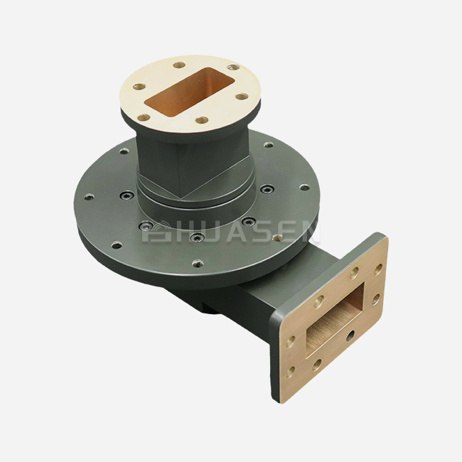
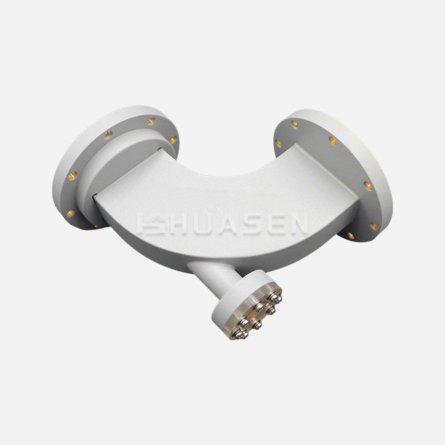
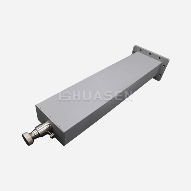
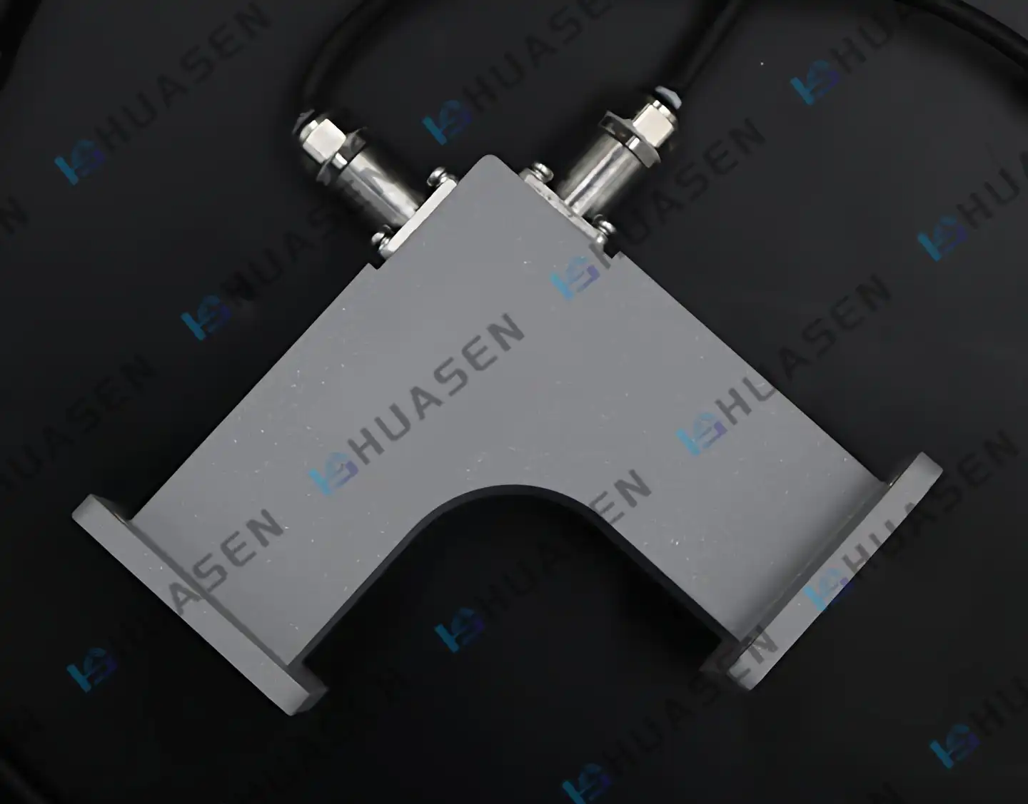
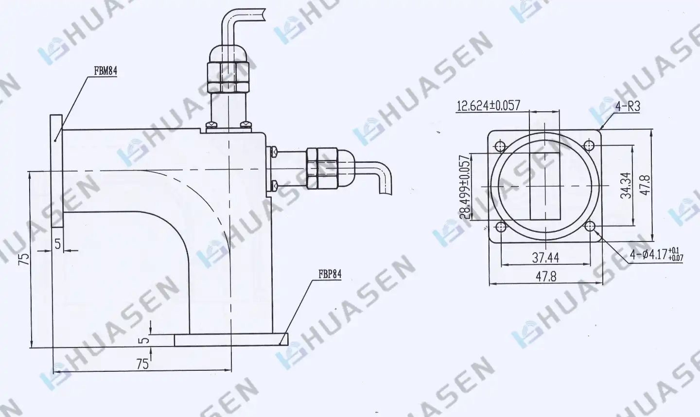
Specialised arc detection waveguides have built-in tracking ports with viewports made of high-purity quartz or sapphire. These optical connections send UV and infrared signals from plasma formation to fibre-coupled photodetectors. This makes microsecond-level reaction times possible, which are very important for keeping expensive amplifier tubes safe. Precision machining and electromagnetic models are used to keep the VSWR below 1.10:1 in the viewport assemblies. This makes sure that the detecting device causes almost no insertion loss.
For electromagnetic field mapping, probe antennas that have been measured are used to measure the patterns of radiation leaks around suspect parts. Three-dimensional field studies pinpoint leak areas to the centimetre level, helping with repairs and proving that the fixes worked. Signal processing methods can tell the difference between direct leaks and reflected environmental clutter. This keeps the reliability of identification in setups with a lot of electrical noise.
Systematic Detection Procedures
Leakage studies that work follow structured steps that start with looking at the system's documents and looking at past failures. Baseline measures set standard values that can be used to compare trends between inspection rounds. The real survey moves in a planned way through the waveguide network, recording results with GPS coordinates and photos that help with making decisions about maintenance. Specialised tools are needed, like field strength metres that are set to national standards, thermal imaging cameras that can find hotspots that can't be seen with the naked eye, and gas leak monitors for tracking pressurised waveguides. These tools make it possible to describe waveguide health in more depth than just a pass/fail way.
Comparing Waveguide Detection with Other Methods
Before making a purchase choice, it's helpful to know how waveguide detection stacks up against other technologies used in industrial inspection. Depending on how the system is set up and what the operational goals are, each method has its own benefits.
Accuracy Versus Coverage Trade-offs
Waveguide detection methods have better spatial clarity and can find leakage sources within millimetres of where two parts meet. This accuracy is very helpful during mending efforts where the cost of fixing something justifies a thorough investigation. Radar-based methods aren't as good at pinpointing locations, but they can quickly check large areas, which makes them good for initial surveys of big networks where coverage is more important than diagnostic detail.
Finding signal leakage in waveguide systems means finding electromagnetic energy that is leaving from waveguide structures without being meant to. This is done by regularly testing and watching the structures. Effective waveguide detection uses advanced diagnostic tools and special optical and electromagnetic sensors to find leaking sources that are caused by physical flaws, failed connectors, or environmental damage. These methods protect the security of the system by keeping the signal strong, reducing interference, and stopping expensive system breakdowns in radar, telecommunications, and satellite communication networks.
Cost-Effectiveness and Integration Considerations
Handheld detection tools don't cost much, but they need to be operated by trained people who can read measurement data and tell the difference between real faults and environmental artefacts. Installing permanent automated monitoring systems within waveguide networks provides continuous surveillance at a higher starting cost. This is supported by the fact that inspection work is reduced and fault response times are sped up in mission-critical installations.
Different detection systems have very different levels of integration difficulty. Waveguide arc detectors don't need many changes to the system because they can be mounted using standard WR-series flange connections and don't add reflection factors that hurt transmission performance. On the other hand, distributed fibre-optic detecting systems need cables to be installed along waveguide runs, which makes the mechanical design more complicated and increases the number of ways it could fail. Environmental flexibility decides whether deployment is possible in a variety of situations. Extreme temperatures and radiation exposure are common in military and defence uses. Optical sensors can handle these conditions and keep their calibration stability when electronic instruments would fail. When made from corrosion-resistant materials and sealed against water entry according to IP67 standards, electromagnetic probes work effectively in humid marine settings.
Procurement Insights: Selecting the Right Waveguide Detection System
When you do strategic procurement, you have to compare technical standards to practical needs while also taking lifecycle costs and supplier skills into account. The following things should be thought about when choosing waveguide detection options that offer measurable value.
Technical Compatibility and Performance Metrics
Checking the frequency range is the first step in making sure that the system works well together. The monitoring equipment needs to be able to pick up all the working frequencies in the waveguide network, as well as any harmonics that are made by the nonlinear parts. Sensitivity specs set the lowest levels of leaking that can be detected. This directly affects the chance of finding early signs of failure before they get worse. The dynamic range needs to change depending on the power levels that are met. For example, high-power radar systems need sensors that can work even when there are problems during measurement. Waveguide standards must be met at the physical contacts, whether they are WR-series rectangular guides, circular configurations, or coaxial transitions. Connector compatibility—SMA, Type-N, K-series, or custom flanges—affects how hard it is to install and how accurately measurements can be repeated. Placement choices are limited by mechanical measurements in places with limited room, such as aeroplane avionics bays or small base station enclosures.
Supplier Evaluation Beyond Price
Project plans are affected by lead times, especially when custom detection systems are made to fit proprietary waveguide designs. OEM makers offer application engineering help during the development of specifications, and approved distributors can get catalogue goods to you faster. For multi-year contracts, supply chain safety is important, which means evaluating the company's finances and production capabilities. Quality assurance includes more than just part specifications. It also includes calibration certification, test data paperwork, and the ability to track back to foreign standards like MIL-STD, ISO 9001, and RoHS compliance. Suppliers with strict quality systems lower implementation risks by making sure products work consistently and having lower failure rates in the field.
Support Services That Add Value
With installation help, you can make sure that the mounting, wire routing, and initial testing are done correctly and in line with what the maker recommends. Training programmes teach maintenance workers how to fix problems with the tracking technology that is being used, which makes the company less reliant on outside service providers. How quickly after-sales help responds decides how long downtime lasts when technical questions come up, or calibration services are needed. Sample trial programmes let you test them out in real-world settings before committing to large-scale purchases. This approach for lowering risk is especially helpful when adding new detection technologies to old infrastructure, where problems with integration might not be clear from the specs alone. Comprehensive evaluation balancing these factors positions procurement teams to select detection solutions delivering optimal total cost of ownership while meeting performance requirements. The investment in robust waveguide detection saves expensive RF infrastructure assets and keeps operations running, which is very important for the success of the business.
Conclusion
Finding signal loss is an important part of maintaining waveguide systems because it protects investments in infrastructure and makes sure that systems work reliably. Learning about the reasons for leaks, like how materials break down or external pressures, lets you take action before they happen and keep downtime costs to a minimum. Traditional inspection methods and new sensor technologies are used together in modern monitoring techniques. These techniques can meet a wide range of needs in the radar, satellite, and internet sectors. When making purchasing choices, it's helpful to look at all of the technical compatibility, provider skills, and lifecycle support services. Companies that use systematic waveguide detection programmes see changes in how often their systems are available and how consistently they work.
FAQ
1. What equipment do I need to start detecting waveguide leakage?
A calibrated RF field strength metre that covers your working frequencies is needed for basic leakage detection. These metres usually cost between $2,000 and $8,000, based on how sensitive they are and how wide the frequency range they cover. By finding leakage spectral fingerprints, handheld spectrum analysers with directed transmitters make diagnostics easier. Time-domain reflectometry tools and thermal-image cameras are useful for advanced troubleshooting. A lot of businesses start by renting equipment during their initial studies and then buy it once they know what they need and how often they need to check it.
2. How often should waveguide systems be inspected for leakage?
Inspection times depend on how vulnerable the system is to damage and how often it needs to be checked. Outdoor systems in naval or industrial settings need to be visually checked every three months and fully tested once a year. Indoor climate-controlled systems usually need to be inspected every six months. Permanently placed arc detectors that offer real-time security are a good way to keep an eye on high-power radar and satellite communication systems all the time. The number of inspections should go up after bad weather, building work closes, or any operational problems that could cause damage.
3. Can signal leakage affect nearby electronic equipment?
Leaked RF energy pairs into nearby cables, enclosures, and electronic systems, causing interference that can range from a small drop in performance to a full breakdown. Higher noise floors affect sensitive sensors, making it harder to find signals and lowering their quality. When leakage fields cause currents to flow through circuit lines, digital systems may experience bit mistakes or logic upsets. It's hard to follow the rules when leakage goes over the pollution limits set by FCC Part 15 or similar foreign standards. This could lead to fines or limits on operations.
Partner with Huasen Microwave for Reliable Waveguide Detection Solutions
Waveguide Detection problems need knowledge that has been built up over many years of excellent radio engineering and manufacturing. Since 1993, Huasen Microwave has focused on high-frequency RF and microwave components, providing solutions that meet the strict needs of the defence, aircraft, and telecommunications industries. Our waveguide detection products have arc detection systems with precisely machined optical viewports that keep the VSWR below 1.10:1. This makes sure that your monitoring infrastructure doesn't cause any significant signal loss. When procurement teams are looking for a waveguide detection provider, our combined method, which combines making parts and helping with application engineering, is very helpful. For every sensing assembly, we give full calibration data, helium leak test certification, and network analyser proof. Email our sales team at sales@huasenmicrowave.com to talk about your unique detection needs and get creative solutions backed by quick technical help for the life of your product.
References
1. Pozar, David M. "Microwave Engineering, 4th Edition." Hoboken: John Wiley & Sons, 2012.
2. Skolnik, Merrill I. "Radar Handbook, 3rd Edition." New York: McGraw-Hill Education, 2008.
3. IEEE Standard 1527-2018. "IEEE Recommended Practice for the Design of Flexible Busbar Systems for Electric Power Applications."
4. Montgomery, C. G., Dicke, R. H., and Purcell, E. M. "Principles of Microwave Circuits." London: Peter Peregrinus Ltd., 1987.
5. Bhat, Bharathi, and Shiban K. Koul. "Stripline-like Transmission Lines for Microwave Integrated Circuits." New Delhi: New Age International Publishers, 1989.
6. Saad, Theodore S. "Microwave Engineers' Handbook, Volumes 1 & 2." Dedham: Artech House, 1971.
Send Inquiry