High-Power Coaxial Isolator for Transmitter Protection






2026-07-12 22:36:09
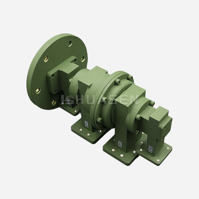
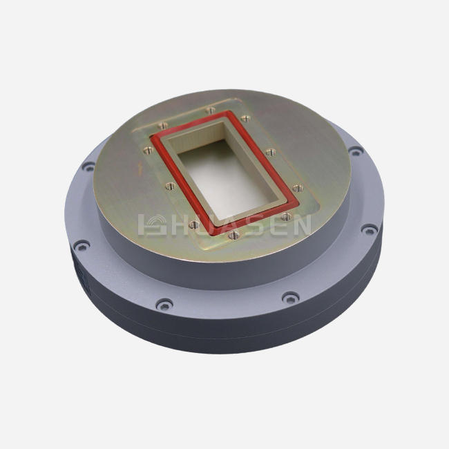
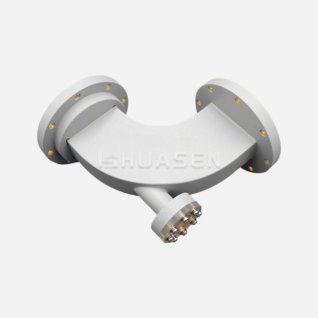
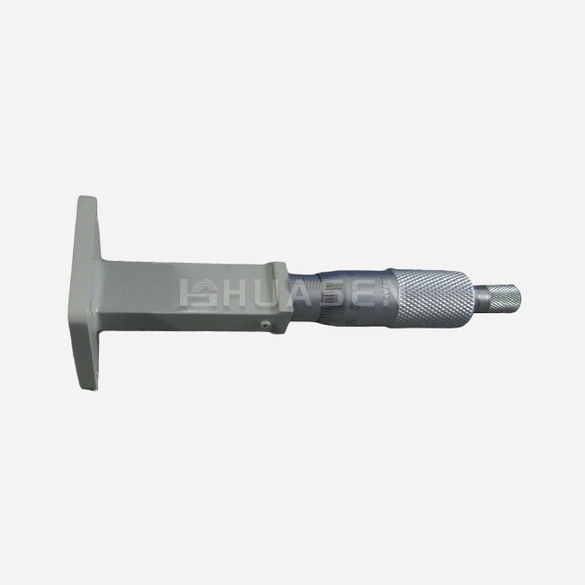
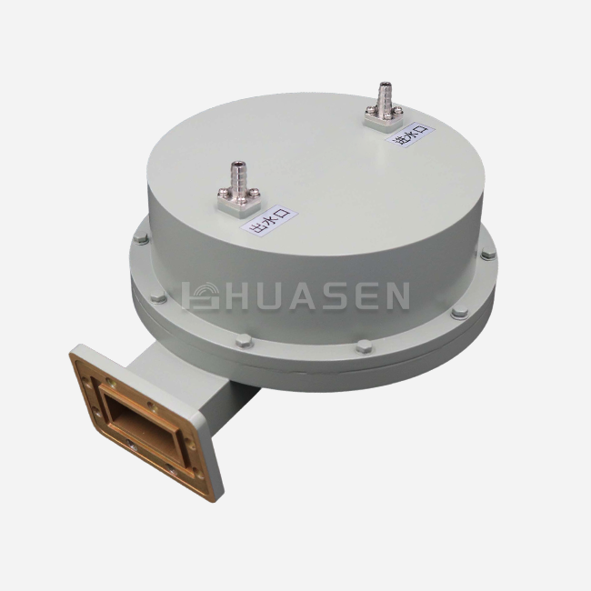
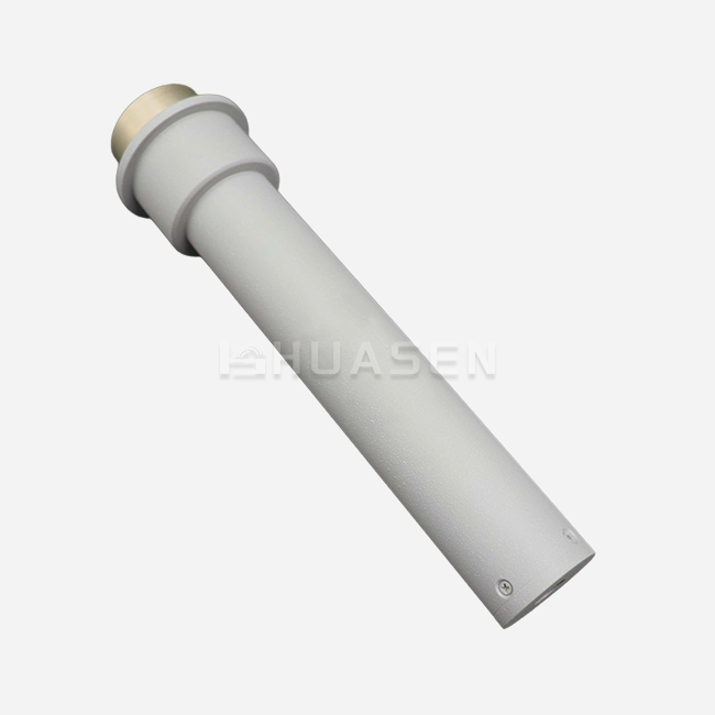
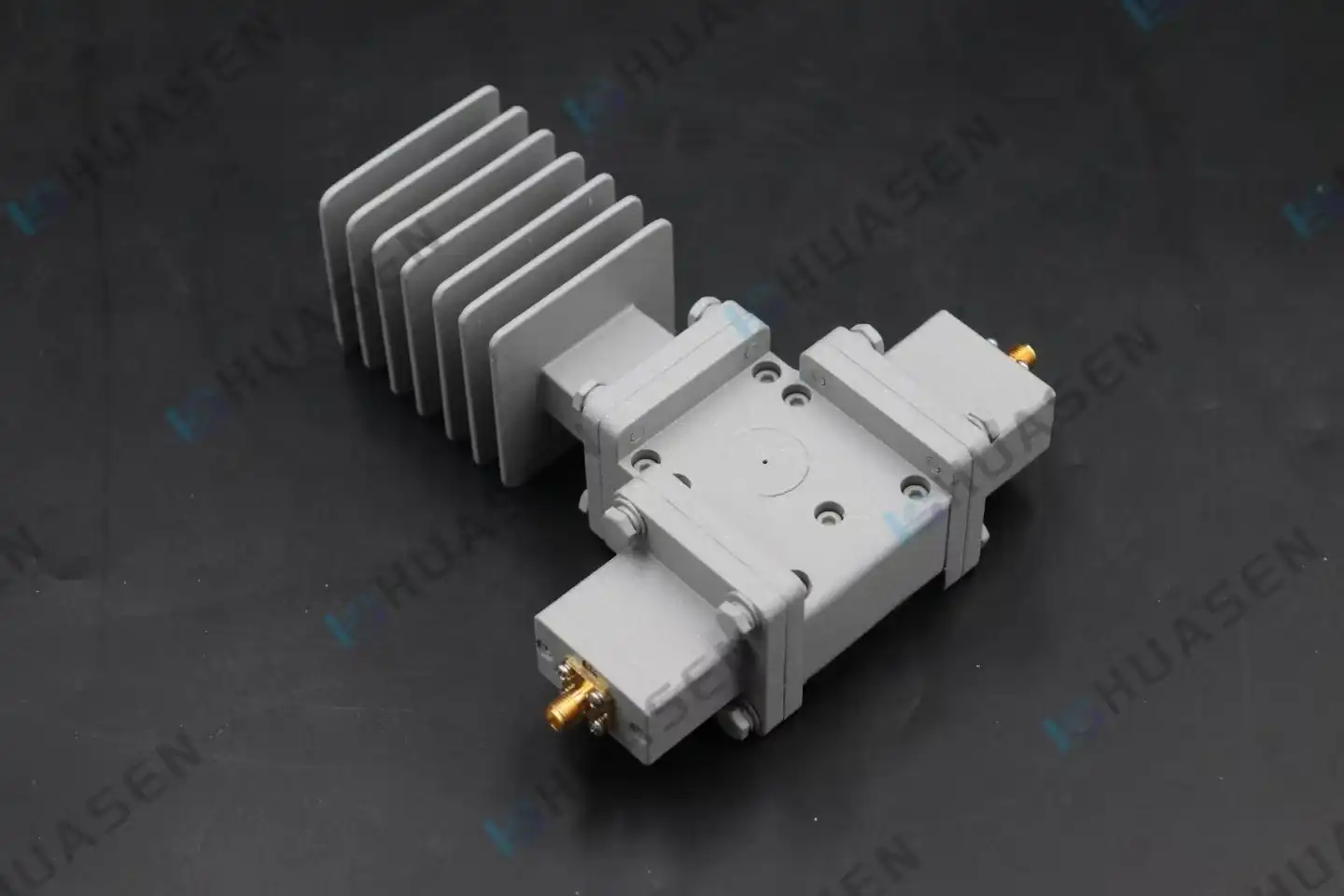
High-power Coaxial Isolators are very important safety shields between transmitters and antennas. They stop harmful reflected energy from hurting expensive amplifier stages. A Coaxial Isolator is an inactive, non-reciprocal device made of ferrite materials and precision coaxial connections that lets signals go forward while absorbing power that goes backwards. When antenna damage, changes in the surroundings, or changes in the load cause impedance mismatches, unprotected emitters are hit by voltage spikes and intermodulation distortion that can destroy power amplifiers for good. Many mission-critical systems have failed because engineers didn't realise how important strong isolation is. This makes this part necessary for defence, aircraft, and telecommunications applications where dependability is a must.
Introduction
Over many years of integrating RF systems, we've learned that protecting transmitters takes more than just knowing about the theory behind it. It also needs methods that work in the real world. When choosing high-power Coaxial Isolators for telecom infrastructure, radar sites, satellite communications, and test equipment, procurement professionals face a number of unique challenges, which are discussed in this manual. You'll learn how these devices work at the component level, what technical specs really matter when buying them, and how to tell the difference between reputable sellers and those who offer poor solutions. The reflected power damage we've seen in systems that aren't secured costs businesses millions of dollars in lost time and repair costs. Understanding isolator technology is important for avoiding catastrophic breakdowns and maintaining long-term system stability, whether you're choosing parts for 5G base stations or keeping lab-grade signal producers safe.
Understanding High-Power Coaxial Isolators and Their Role in Transmitter Protection
How Passive Isolation Protects Active Components?
A Coaxial Isolator works by using Faraday rotating principles in magnetised ferrite material, which creates directional electromagnetic behaviour that seems almost strange. Forward signals are attenuated very little (usually less than 0.5dB insertion loss), while backward signals are attenuated by 20dB or more. Power amplifiers are protected from load mismatches that would otherwise cause standing waves along transmission lines by this non-reciprocal property. If antenna systems get ice buildup, get damaged, or just work outside of their designed frequency range, the resulting changes in resistance send energy back toward the source. If there is no isolation, this reverse power causes voltage antinodes that are higher than the transistors' breakdown rates. This destroys the output stages right away during high-power transmission.
Quantifying Isolation Performance Metrics
We measure how well an isolator works by three basic factors that have a direct effect on how long an emitter lasts. Isolation standard shows the ability to absorb reverse power, and most telecommunications applications need at least 20dB of performance to protect solid-state amps properly. Insertion loss measures how much the forward signal is degraded, and for large-scale deployments, every 0.1dB increase means real gains in efficiency. If the VSWR is less than 1.25:1, the isolator won't add any extra echoes that make system problems worse. These measurements change over time; for example, low VSWR makes isolation less effective, while high insertion loss makes transmitters less efficient. The Coaxial Isolators from Huasen Microwave meet these performance goals across frequency bands from 0.33GHz to 3.1GHz, with insertion loss kept below 0.4dB and isolation above 22dB the whole time they're working.
Thermal Management in High-Power Environments
The reverse power that is received by the isolator turns into heat inside the termination load, so thermal design is very important for durability. To handle up to 200W of average power, you need to use complex heat-dissipation methods that keep ferrite magnets from losing their magnetic properties and resistors from breaking. All-aluminum construction of the housing gives it strength and great thermal resistance, which moves heat away from sensitive magnetic parts. We've seen that bad thermal design leads to center frequency drift and isolation degradation as the working temperature rises. These problems show up gradually in the field, not during the initial tests. Because ferrite materials have a temperature coefficient, their performance changes between -40°C and +85°C unless a balancing magnetic circuit design keeps them working steadily in all temperatures.
Technical Dimensions and Types of Coaxial Isolators
Frequency Band Coverage and Application Matching
Coaxial Isolators work as resonant devices, which means that because of their limited bandwidth, they need to be carefully chosen for specific uses. In the L-band (1-2GHz) range, isolators protect wireless backhaul lines and weather radar emitters. In the S-band (2-4GHz) range, they serve GPS systems and mobile satellite communications. For huge MIMO antenna arrays to work in the 5G revolution, they need to cover the C-band (3.3–4.2GHz) and be able to handle a lot of power while still being small. We make isolators that work best across small bandwidths of about 5% to 20% of the center frequency. They can handle frequencies from very high frequency (VHF) to very high frequency (Ka-band). If you try to run an isolator outside of its designated range, it will collapse catastrophically, letting reverse power flow easily and removing all transmitter security.
Distinguishing Isolators from Circulators and Couplers
Understanding the differences between components helps you avoid buying mistakes that hurt system design. Circulators have three ports that send signals in a certain order: port one to port two, port two to port three, and port three to port one. This makes them perfect for transceiver diplexing, which is when the broadcast and receive lines share antenna connections. When the third port is closed off by a matching load resistor inside the isolator, it works like a Coaxial Isolator with the third port terminated internally and turns the energy that port receives into heat. Directional couplers take samples of either forward or backward power to help with tracking, but they don't actually protect against isolation. Because of the way the internal termination works, isolators can usually only handle a lower amount of reverse power than their forward power limit. For example, a device that can handle 200W of forward power might only be able to handle 20W of constant reverse power before it gets too hot.
Connector Interface Standards and Mechanical Considerations
Interfaces have a big effect on how well high frequencies work and how flexible installations can be. It has been shown that SMA connections work reliably up to 18GHz, while N-Type connectors can handle higher power levels and are built to last in harsh outdoor conditions. It is possible to use millimeter-wave frequencies up to 40GHz with precision 2.92mm connections, but their delicate contact mechanisms need to be installed with care. Our isolators are made with standard flange mounting holes that make them easy to fit into equipment racks and RF systems. The all-aluminum case blocks electromagnetic interference (EMI) while keeping the weight low enough for use in flight, where every gram counts. Connector gender, thread type, and direction all affect how the installation is done. These may seem like small issues when they are being specified, but they become very important when they are being used in the field, and physical limitations arise.
Choosing the Best High-Power Coaxial Isolator for RF and Microwave Applications
Evaluating Power Handling Specifications
Forward power numbers show how much constant RF power an isolator can send without losing its performance. Our 200W average power standard comes from safe thermal design reserves that keep the system stable during long gearbox cycles. Peak power rates are just as important for pulsed radar uses, where rapid power levels are 10 times or more higher than usual values. The reverse power specification shows the thermal bottleneck in the isolation system. The amount of energy that is received and lost as heat in the termination load is limited by the resistor's wattage and its ability to transfer heat. Customers have bought isolators based only on their forward power ratings, only to find that they didn't work when antenna problems sent a lot of reverse energy into the device. Full datasheets must show how to handle both forward and backward power across the whole temperature range, not just at room temperature.
Balancing Performance Against Physical Constraints
Installation room constraints often play a bigger role in choosing components than electricity requirements. Compact designs make tools smaller, but they might not be as good at handling power or heat. Our engineering team addresses these different needs by using advanced ferrite formulas and magnetic circuit layouts that are optimised to get the most out of limited space. The way the device is mounted affects how well it cools. For example, horizontal installation lets air flow naturally across the housing surfaces, while vertical installation might need forced air cooling to handle the same amount of power. When it comes to air travel and space travel, where every part goes through strict mass planning, weight becomes the most important factor. For shipboard or vehicle-mounted setups, the need for mechanical strength adds structure reinforcement that makes the system heavier and costs more.
Supplier Evaluation and Quality Assurance
When choosing component providers, you have to look at more than just marketing claims to see how well they can make the parts. The fact that Huasen Microwave Technology was founded in 1993 shows that it has been dedicated to making RF and microwave components for a long time. They have 30 years of experience making ferrite devices and Coaxial Isolator. Our ISO-certified manufacturing methods make sure that each batch of products is the same, which is very important for system designers who are putting thousands of units into telecommunication networks. When you look at a datasheet, you should look at S-parameter plots for all temperature and power levels, not just readings at room temperature. We give you all the test results that show the limits of the performance for insertion loss, isolation, and VSWR. These limits set the promised specs. Custom frequency bands, power levels, and connection configurations show that engineers are flexible enough to meet the needs of each application. Technical help that is quick to respond during the design phase keeps mistakes from happening during system integration that cost a lot of money.
Practical Applications and Case Studies of High-Power Coaxial Isolators in the Field
Protecting 5G Base Station Amplifiers
Massive MIMO antenna systems use 64 or more broadcast chains inside a single active antenna unit. This is where protecting each amplifier becomes economically important. To avoid mutual coupling effects and damage from load change, each power amplifier needs to be separated from its own radio element. We provided isolators for a large metropolitan 5G rollout. During the first six months, 8% of the amplifiers that weren't properly isolated failed in the first installs. Failure rates dropped below 0.5% per year after the right Coaxial Isolators were added to all of the antenna arrays. This meant that expensive tower climbs were no longer needed to repair parts. Isolation stopped reflected power from radio elements that were loaded with ice in the winter, so the network stayed online during bad weather, when communication services are most needed.
Radar Transmitter Chain Protection
For defence purposes, active electronically scanned array radar systems must be completely reliable even in difficult electromagnetic circumstances. Transmit-receive units that use hundreds of watts per element need separation that keeps working even when temperatures are very high or very low and when vibration levels are higher than what is normally required by industry standards. Together with a radar system integrator, we fixed early failures in marine surveillance sites along the coast caused by salt fog that harmed antenna performance. The higher antenna VSWR would have killed amplifiers that weren't shielded, but isolators with the right rating took in the reflected energy and kept the system running. The measurement results showed that the isolation performance stayed above specification even after being tested in MIL-STD-810 environments. This proved the design gaps that commercial-grade parts couldn't reach.
Laboratory Test Equipment Safeguards
Vector network analysers and RF signal generators are big expenses that need to be kept safe from human error and strange behaviour from the object being tested. During device characterisation, test labs often connect these instruments to impedances they don't know, which can damage sensitive port circuits through reflection. Putting in external Coaxial Isolators at important test points keeps the calibration accurate by providing a constant source impedance and avoiding expensive instrument fixes. We gave isolators to a university research lab that was measuring high-power antennas and had student researchers connect loads that were very badly wrong from time to time. The isolators took in the reflections without damaging them, so the training program could go on while the six-figure investments in test tools were safe.
Conclusion
High-power Coaxial Isolators are very important for protecting against emitter breakdowns that could shut down defence systems, communication networks, or industrial processes. The technical factors we looked at—frequency coverage, power handling, separation performance, and heat management—directly affect how reliable a system is and how much it costs to run. With 30 years of experience in specialised production, Huasen Microwave makes isolators that meet the strict requirements of telecoms infrastructure, aerospace platforms, and laboratory instruments. Our designs, which cover frequencies from 0.33GHz to 3.1GHz, can handle 200W of power and have better cooling properties, solving the problems engineers actually face when putting together systems. To do a good job of buying, you need to know how the electrical requirements, mechanical limitations, and source skills affect each other and how they affect long-term performance and value.
FAQ
1. What distinguishes high-power isolators from standard models?
Higher-power Coaxial Isolators have better heat management thanks to bigger ferrite volumes, stronger internal termination loads, and better heat escape paths that can handle 100W to 200W of continuous forward power. Standard types usually have power ratings below 50W, come in smaller sizes, and can't cool as well. The magnetic circuit design is very different. High-power units use rare-earth magnets and temperature-compensated ferrite grades that keep working even when exposed to heat, which would normally demagnetise standard isolators.
2. How do I verify isolation performance before purchase?
Ask for S-parameter data that was collected across the whole temperature range you gave, not just at room temperature. Manufacturers who are serious about what they do show lines that show isolation versus frequency at both the lowest and highest working temperatures. We include the results of swept power tests that show the standards are met at the stated power levels. Independent proof using certified vector network analysers backs up what the datasheet says, but it takes the right test tools and measurement know-how to do this.
3. Can isolators integrate into existing RF systems seamlessly?
To integrate things correctly, you need to match the types of connectors, frequency bands, and power levels to the way the system works. The 50-ohm impedance standard makes sure that most RF communication tools can work with each other. Installation room requirements must be met by the physical mounting holes and connection orientations. We give you dimensional models and connector specs to help you check the mechanical design before you commit to buying something. When standard goods don't meet the needs of the system design, custom setups solve specific integration problems.
Partner with a Trusted Coaxial Isolator Manufacturer
Huasen Microwave has the high-power RF separation options that your important systems need. Our engineers have thirty years of experience with ferrite devices, which they use to make sure that every Coaxial Isolator they make protects your receivers from harmful mirrored power. Our product line is made of only aluminium and has careful thermal design limits that allow it to run continuously at 200W in harsh environments that would normally damage lesser components. System integrators, procurement experts, and RF engineers are welcome to talk to our technical sales team about unique application needs. You can email us at sales@huasenmicrowave.com to get full datasheets, quotes for unique frequency bands, or sample units to test and evaluate. Your gearbox chain's dependability depends on parts that are designed to work well together. Let us show you why top defence contractors and telecommunications companies choose Huasen Microwave isolators for their toughest jobs.
References
1. Pozar, David M. Microwave Engineering, 4th Edition. Hoboken: John Wiley & Sons, 2012.
2. Linkhart, Douglas K. Microwave Circulator Design, 2nd Edition. Norwood: Artech House, 2014.
3. Helszajn, Joseph. The Stripline Circulators: Theory and Practice. Hoboken: Wiley-IEEE Press, 2008.
4. Baden Fuller, A.J. Ferrites at Microwave Frequencies. London: Peter Peregrinus Ltd., 1987.
5. Seymour, Benjamin Cory. Passive RF and Microwave Components in Defense and Telecommunications. Cambridge: MIT Technical Review Press, 2019.
6. International Telecommunication Union. ITU-R Recommendation SM.329-12: Unwanted Emissions in the Spurious Domain. Geneva: ITU Radiocommunication Sector, 2019.
Send Inquiry