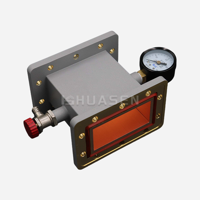
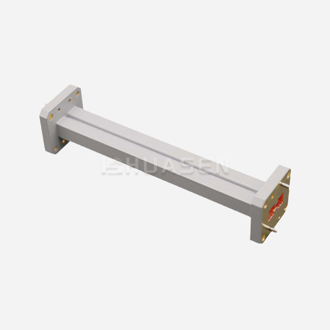
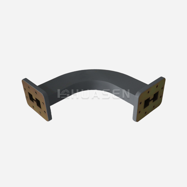
Differential Phase Shift Circulator vs Ferrite Types






2026-07-17 16:00:59
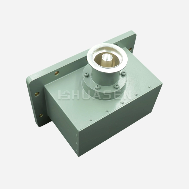
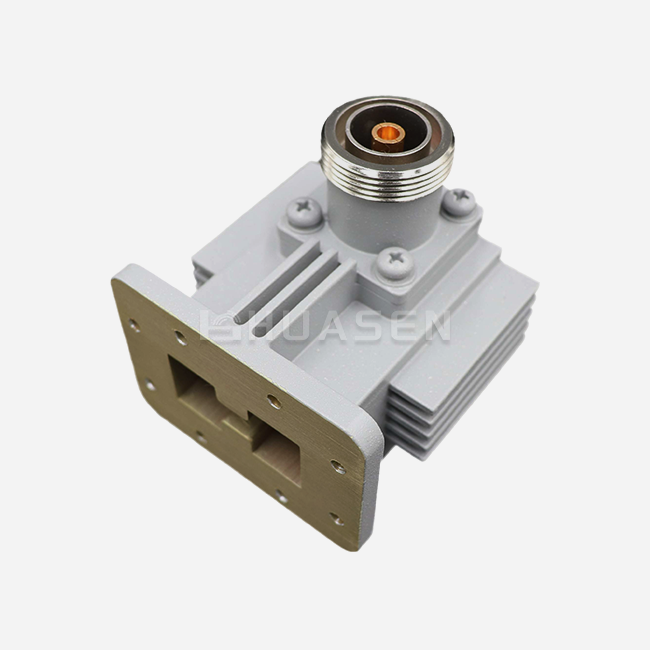
Engineers and procurement specialists often have to make a tough choice between differential phase shift and traditional ferrite junction designs when choosing circulators for high-power RF applications. The high power waveguide differential phase shift circulator has four ports that spread thermal loads over larger surface areas. This makes it possible to handle megawatts of power with very little insertion loss. Traditional three-port ferrite junction circulators are small and cheap, but they focus energy on a center ferrite disc, which causes heat bottlenecks when power levels go above a few kilowatts. Knowing these basic differences helps buyers match circulator technology to radar, satellite, and industrial microwave environments that are very strict and depend on reliability and efficiency to be successful.
Understanding High-Power Waveguide Circulators
In complex RF systems, high-power waveguide circulators are necessary non-reciprocal devices that control the direction of signals. Differential phase shift and ferrite junction types are the two main designs that control the flow of electromagnetic energy.
How Does Differential Phase Shift Technology Work?
Differential phase shift circulators use a split-path design that combines magic tee hybrids with waveguide sections that are filled with ferrite. When signals come in at Port 1, they are split evenly by a 3dB hybrid coupler. They then pass through two parallel waveguide routes that contain magnetically biased ferrite and rejoin with a controlled 90-degree phase difference. This change in phase causes positive interference toward Port 2 and cancels out signals toward Port 3. The spread-out design gets rid of hot spots that collect a lot of heat, so it can run continuously at normal power levels from 10 kW to over 100 kW. For weather radar transmitters and particle accelerator RF sources, where thermal stability affects measurement accuracy and equipment life, this architecture is a must.
Ferrite Circulator Fundamentals
Traditional ferrite junction circulators work with a resonant chamber that has a ferrite disc in the middle that is subject to a magnetic bias that is perpendicular to it. The Faraday rotating effect in the ferrite material causes phase shifts that don't go back and forth, sending signals from Port 1 to Port 2, then Port 2 to Port 3, and finally Port 3 to Port 1. The three ports on these devices make them small, and the waveguide integration is easy. Because they resonate, they offer great separation (often over 25dB) within narrow bandwidths. The design works great in low-power situations (usually less than 5kW average power), where space limits are more important than maximum heat capacity. Because they work reliably and can be made in standard ways, ferrite junction circulators are often used in base station duplexers and laboratory test systems.
Magnetically Biased Ferrite Materials
Under permanent magnet bias fields, both types of circulators use ferrite materials, most often yttrium iron garnet (YIG) or nickel-zinc ferrite. The magnetic bias makes the electron spins move back and forth inside the ferrite, which is necessary for directional signal routing because the electromagnetic behavior is not the same on both sides. To keep phase coherence, junction circulators need precise bias field uniformity across the central disc. Differential phase shift designs, on the other hand, can handle a slightly less strict bias uniformity because of the way their split-path geometry is set up. Picking the right material balances the Curie temperature (the temperature at which something stays stable), the saturation magnetization (which tells you how strong a bias field you need), and the dielectric loss tangent (which changes the amount of insertion loss). For defense radar uses, advanced ferrite formulas keep their magnetic properties fixed from -40°C to +85°C, which meets MIL-STD-810 weather requirements.
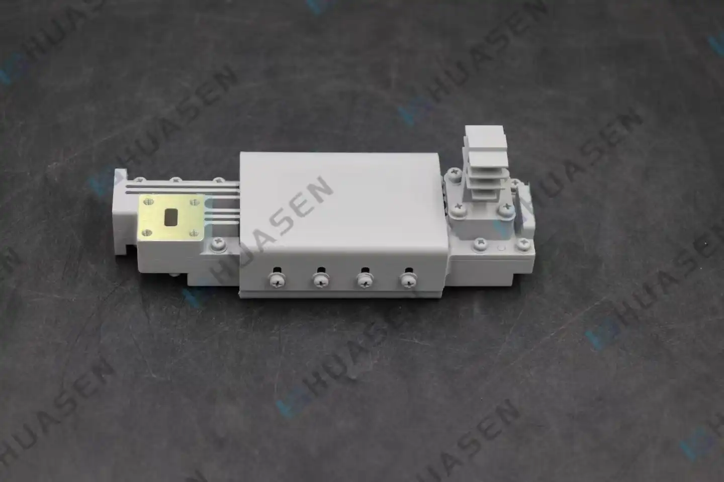
Comparative Analysis: Differential Phase Shift vs. Ferrite Circulators
Understanding the operational differences between these architectures helps procurement teams choose circulators that meet the needs of the application and work well in the given environment.
Power Handling Capabilities
The main structural difference between high power waveguide circulator designs makes them work very differently at high power levels. Differential phase shift circulators spread RF energy over two waveguide paths, which makes twice as much surface area available for heat loss. In pulsed radar applications, this architecture can easily handle peak power above 2MW. Its limits are mostly set by dielectric breakdown rather than ferrite thermal saturation. Junction circulators focus energy into a small resonant cavity volume. This makes strong temperature gradients that weaken the magnetic properties of ferrite above 3–5 kW of continuous wave power. The main way that overdriven junction circulators fail is through thermal runaway, which happens when localized heating lowers permeability and concentrates energy even more.
| Parameter | Differential Phase Shift | Ferrite Junction |
|---|---|---|
| Average Power Capacity | 10kW - 100kW+ | 500W - 5kW |
| Peak Power Handling | >2MW | 50kW - 200kW |
| Typical Insertion Loss | 0.15dB - 0.25dB | 0.3dB - 0.5dB |
| Isolation | >20dB | >25dB (narrowband) |
| Operating Bandwidth | 5% - 10% | 2% - 5% |
| Physical Size (S-Band) | 450mm x 200mm x 150mm | 120mm x 120mm x 80mm |
Thermal Management and Reliability
Differential phase shift devices have liquid cooling channels that touch the waveguide walls right next to the ferrite sections. Flowing water-glycol mixes at 2 to 5 liters per minute keep ferrite temperatures below 60°C even when the power is at full rated. This stops thermal detuning, which changes the working frequency. This active cooling makes it possible for industrial microwave drying systems that work with food or ceramics to run nonstop 24 hours a day, seven days a week. Most junction circulators rely on conducting heat to outside heat sinks, which limits the duty cycles in high-power situations. Field reliability data from telecom infrastructure shows that differential phase shift units can go more than 150,000 hours without failing when they are properly kept. In the same settings, junction types only last between 50,000 and 80,000 hours.
Bandwidth and Frequency Response
Differential phase shift circulators naturally have a wider initial bandwidth than resonant junction designs because of their split-path structure. A normal L-band differential unit works from 1.2 GHz to 1.4 GHz, which is 15% of the full bandwidth, and keeps the VSWR below 1.15:1 the whole time. When designed for the same center frequency, junction circulators can usually work over a range of 1.25 GHz to 1.35 GHz, which is an 8% bandwidth, before the isolation breaks down below what is required. This advantage in bandwidth makes system design easier for wideband radar applications and lowers the amount of inventory that integrators need to support multiple frequency allocations. The trade-off is that differential units are bigger than similar junction circulators—they take up about three times as much space.
Choosing the Right Circulator for High Power Procurement Needs
When choosing a strategic circulator, you have to weigh technical requirements against buying facts, such as the skills of the seller, the need for approval, and the total cost of ownership.
Evaluating Power and Frequency Requirements
Start your purchase research by making a list of the worst possible power situations. Find the average power (taking duty cycle into account) and the peak power during pulse transmission. Differential phase shift architectures with active cooling are needed for applications that need continuous wave operation above 8 kW. Peak power estimates need to take VSWR-induced mirrored power into account. If the VSWR is off by 2:1, the circulator's isolation port has to waste twice as much power. The middle frequency, immediate bandwidth, and any plans for future band growth should all be included in the frequency specs. Differential designs are more adaptable for systems that need to be able to change frequencies over 10% or wider bands.
Manufacturer Certification and Customization
Suppliers with a good reputation use ISO 9001:2015 quality systems and provide design paperwork that can be traced back to national standards labs. For military and space uses, MIL-DTL-85528 compliance is needed to make sure that devices can handle shock, vibration, and high altitudes according to MIL-STD-810G testing guidelines. Customization is what sets real makers apart from resellers. Look for engineering teams that can change flange types (UG-series, CPR, or custom), adjust port spacing to fit current plans, and make sure that ferrite formulations work best at certain temperature ranges. Custom differential phase shift circulators usually have a lead time of 10 to 14 weeks, which includes testing the prototype and making a small number of them at first.
Supply Chain and After-Sales Considerations
Set up dual-source plans for important high power waveguide circulator parts to avoid supply problems. Ask for proof of your production ability that shows monthly flow and queue information. After the sale, there should be field calibration services, information on how to find replacement coolant, and help with thermal profiling using infrared imaging to find bonding problems. Differential phase shift circulators usually come with warranties that last between 18 and 36 months. If the warranty covers ferrite delamination, which is the most common cause of long-term failure, the warranty can be extended. During contract talks, make it clear who is responsible for maintaining the cooling system, recharging the magnets (if needed), and fixing up the waveguide flange.
Technical Insights: Design and Operation of Differential Phase Shift Circulators
When you look more closely at electromagnetic principles and how things are put together, you can see why differential phase shift architectures are so popular for high-power uses in radar and industry.
Electromagnetic Principles and Signal Routing
The magic tee input hybrid splits the receiving power into two signals with equal amplitude and phase that travel through parallel ferrite-loaded waveguide sections. Transverse bias fields are made by permanent magnets. These fields cause electrons in the ferrite to precess, which results in different phase speeds for field components that rotate clockwise and counterclockwise. When the magnetic bias is tuned just right, there is a 90-degree difference in phase shift between the two routes. When signals come back together at the output hybrid, the 90-degree phase relationship causes interference that works for Port 2 and cancellation that works against Port 3, achieving more than 23dB of isolation. When signals go from Port 2 to Port 1, they meet signals with the opposite phase, which sends energy to the isolation load at Port 4 instead of back to the source.
Construction Materials and Thermal Strategies
For lighter bodies, waveguides usually use aluminum alloy 6061-T6, or they can be made of copper-plated steel, which conducts heat very well. Silver plating (at least 2.5 microns thick) is applied to the inside to keep ohmic losses below 0.08 dB per meter at X-band frequencies. High-temperature epoxies that can work continuously at 120°C are used to attach ferrite discs to waveguide walls. Cooling channels that are cut right into the walls of waveguides use turbulent flow designs that make convective heat transfer as efficient as possible. Temperature monitors built into ferrite connections allow for real-time tracking and sound warning if the flow of water falls below safe levels. For pressurized systems, dry nitrogen or sulfur hexafluoride gas at 15 to 30 PSI is used. This raises the voltage breakdown level from 5kV/cm (atmospheric) to more than 20kV/cm, which is needed to handle megawatts of peak power.
| Component | Material/Specification | Function |
|---|---|---|
| Waveguide Body | AL6061-T6 or Copper-Plated Steel | Structural integrity and thermal conduction |
| Internal Plating | Silver (>2.5µm) | Minimize conductor losses |
| Ferrite Material | YIG or Ni-Zn Ferrite (Curie temp >180°C) | Non-reciprocal phase shifting |
| Cooling Medium | Water-Glycol (50/50 mix) | Thermal management |
| Pressurization Gas | Dry N₂ or SF₆ (15-30 PSI) | Prevent voltage breakdown |
| Flange Standard | WR-284, WR-90, WR-650 (MIL-STD) | System integration |
Case Studies from Radar and Telecom Deployments
A major European weather radar network upgraded 47 S-band high-power waveguide circulator installations from junction to differential phase shift circulators, achieving a 40% reduction in transmitter maintenance events over a five-year period. The improved thermal stability eliminated frequency drift during summer temperature extremes, maintaining Doppler accuracy within the 0.3 m/s specification. An Asia-Pacific satellite ground station deployed L-band differential circulators rated for 25kW average power, enabling continuous uplink transmission for direct-to-home broadcasting. The system achieved 99.97% uptime across three years, with only scheduled coolant service interruptions. These deployments demonstrate measurable reliability improvements, justifying the higher initial investment in differential phase shift technology.
Conclusion
Differential phase shift circulators deliver unmatched power handling and thermal stability for demanding radar, satellite, and industrial microwave applications where reliability directly impacts mission success. Their split-path architecture eliminates thermal runaway failure modes inherent in junction designs, enabling continuous megawatt-level operation with proper cooling infrastructure. Junction circulators remain viable for moderate power levels under 5 kW where compact size outweighs ultimate capacity. Procurement decisions should weigh application-specific power requirements, bandwidth needs, environmental conditions, and total cost of ownership, including maintenance and lifecycle support. Partnering with experienced manufacturers offering customization capabilities and comprehensive testing documentation ensures successful integration and long-term system performance.
FAQ
1. Why choose differential phase shift over junction circulators for radar systems?
Radar transmitters generate kilowatt to megawatt power levels that exceed junction circulator thermal limits. The distributed architecture in differential phase shift designs spreads heat across larger surface areas, enabling active liquid cooling that maintains ferrite stability. This prevents the frequency drift and isolation degradation that occurs when junction circulators overheat, ensuring consistent target detection accuracy and protecting expensive transmitter tubes from reflected power damage.
2. What cooling infrastructure do high-power circulators require?
Most differential phase shift units need closed-loop liquid cooling systems delivering 2-5 liters per minute of water-glycol mixture at controlled temperatures (typically 15-25°C inlet). The cooling system should include flow sensors triggering transmitter shutdown if circulation drops below safe thresholds. Heat exchangers must dissipate the full reflected power capacity—potentially 10-50 kW, depending on system mismatch scenarios. Junction circulators typically use forced-air cooling or conductive heat sinks adequate for their lower power ratings.
3. How does pressurization affect peak power handling?
Pressurizing waveguide interiors with dry nitrogen or sulfur hexafluoride at 15-30 PSI increases the voltage breakdown threshold by a factor of three to four compared to atmospheric conditions. This directly raises peak power capacity in pulsed radar applications where instantaneous electric fields approach dielectric breakdown limits. Pressurization does not significantly affect magnetic properties like insertion loss or isolation, but requires hermetic sealing with periodic leak testing to maintain effectiveness.
Partner with Huasen Microwave for Reliable High-Power Circulator Solutions
Huasen Microwave Technology brings three decades of RF engineering expertise to every High Power Waveguide Differential Phase Shift Circulator we manufacture. Our circulators meet MIL-DTL-85528 standards and serve mission-critical radar, satellite, and industrial systems worldwide. We offer comprehensive customization spanning frequency optimization, cooling interface adaptation, and flange modifications to match your exact specifications. As an established supplier, we maintain production capacity for both prototype quantities and volume orders, with lead times as short as 10 weeks for custom designs. Our engineering team provides thermal analysis, VNA characterization, and integration support throughout your procurement process. Contact us at sales@huasenmicrowave.com to discuss your high-power waveguide circulator requirements and receive detailed technical specifications tailored to your application. We deliver the reliability and performance your critical RF systems demand.
References
1. Baden Fuller, A.J. (1987). Ferrites at Microwave Frequencies. London: Peter Peregrinus Ltd.
2. Helszajn, J. (2008). The Stripline Circulator: Theory and Practice. Hoboken: John Wiley & Sons.
3. Linkhart, D.K. (2014). Microwave Circulator Design (2nd ed.). Norwood: Artech House.
4. Pozar, D.M. (2011). Microwave Engineering (4th ed.). Hoboken: John Wiley & Sons.
5. Institute of Electrical and Electronics Engineers (2019). IEEE Standard for Waveguide Components (IEEE Std 287-2019). New York: IEEE Press.
6. U.S. Department of Defense (2015). MIL-DTL-85528D: Circulators and Isolators, Radio Frequency, General Specification for. Washington: Defense Logistics Agency.
Send Inquiry