Coaxial Directional Coupler Technologies for Modern Communications






2026-07-23 16:47:12
Modern RF and microwave communication systems rely on precise signal management, and coaxial directional coupler technologies deliver exactly that—enabling engineers to sample, monitor, and measure electromagnetic signals without interrupting transmission paths. These passive devices extract a predictable fraction of power traveling in one direction while isolating reflected signals, solving critical challenges in 5G base stations, satellite links, radar systems, and test laboratories. Understanding their operation, selection criteria, and procurement strategies empowers B2B decision-makers to optimize system performance and cost-effectiveness.

Understanding Coaxial Directional Couplers – Theory and Key Functions
What Is a Coaxial Directional Coupler, and How Does It Work?
A coaxial directional coupler is a very accurate passive RF device that picks up electromagnetic power moving along a transmission line in a certain direction while keeping signals going in the opposite direction very far away. This part, unlike basic power splitters, separates waves that come in (forward) from waves that come back (reverse). This is necessary for real-time signal monitoring, automatic level control loops, and VSWR measurements in high-power transmitters. A secondary transmission line runs alongside the main line inside a shared building. This is how electromagnetic coupling works. Electric and magnetic fields interact with these lines to send and receive energy. The coupling openings, or close gaps, control this process.
Critical Performance Parameters Explained
Technical specs describe how well these gadgets work in tough conditions. The coupling factor, which tells you how strong the sampling signal is compared to the main line, is between 10 dB and 50 dB. Directivity is a measure of how well the coupler can tell the difference between forward and mirrored signals. Good units get 20dB to 30dB or better, which has a direct effect on how accurate the measurements are. To keep the main signal's integrity, insertion loss stays low (usually less than 0.5 dB when coupling loss is taken into account). If the VSWR is less than 1.25:1, there will be almost no echoes at the input and output ports. Based on the design, the frequency ranges from 30 MHz to 40 GHz, and broad types can handle more than one octave.
| Parameter | Typical Range | Importance |
|---|---|---|
| Coupling Factor | 10–50 dB | Finds the level of the sampling sound |
| Directivity | 20–30 dB | Separates forward and backward waves |
| Insertion Loss | <0.5 dB | Keeps the main signal strong |
| VSWR | <1.25:1 | Cuts down on port reflections |
| Frequency Range | 0.03–40 GHz | Sets the working speed |
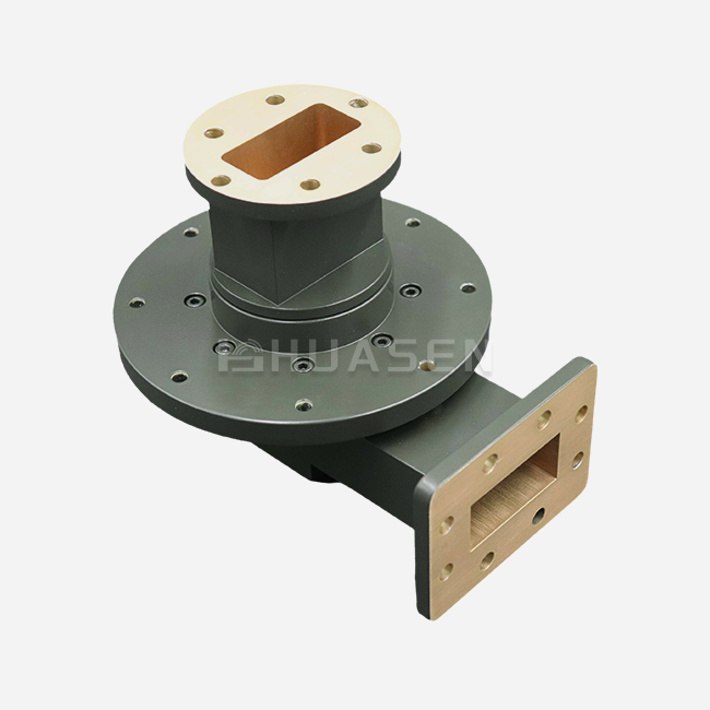
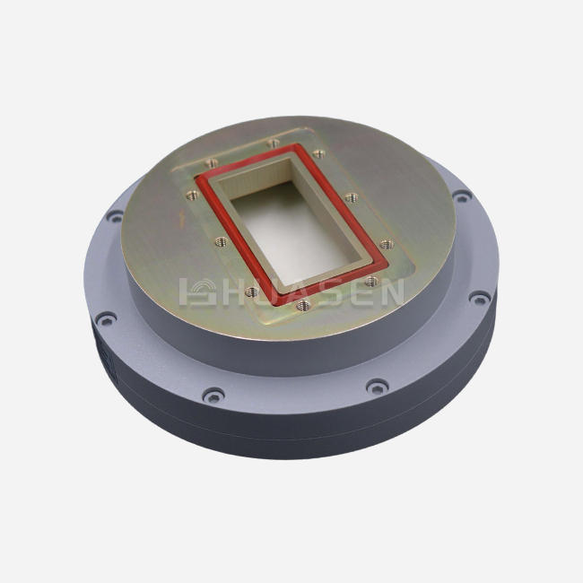
Precision-machined aluminium or brass housings are used in the physical build, and silver or gold finishing is used to reduce skin effect losses. PTFE or air dielectrics keep temperatures stable at all temperatures. There are different types of connectors, such as N-type, SMA, 2.92mm, and K-type, to fit different system architectures. Fully sealed designs keep moisture, dust, and rust out of internal parts, which is very important for base stations and marine communication systems that are installed outside.
Advantages Over Alternative Coupling Technologies
Compared to waveguide couplers, coaxial versions are smaller and cover a wider range of frequencies. This makes them easier to install in equipment racks with limited room. The need to place stripline couplers on a printed circuit board limits their ability to handle power and work in harsh environments. Hybrid couplers can't tell the difference between directions, which is needed for accurate measurements of reflection. The coaxial architecture strikes a good mix between speed, size, and flexibility. This is why it is the best choice for infrastructure for telecommunications, radar in space, and lab test equipment that needs to be reliable and accurate.
Comparison and Selection: Choosing the Right Coaxial Directional Coupler for Your Application
Evaluating Different Coupler Types for Your System
Multiple coupler designs are available to procurement teams, and each one works best in a certain working setting. Standard Type (CC) couplers are used for general monitoring jobs in controlled settings. They provide good performance for both power sampling and VSWR checks. High Power Type (CHPC) versions can handle average steady power levels of up to 500W, which is important for base station transmitters and radar amps that need to handle high power and keep their temperature under control. Bidirectional Type (CDC) couplers watch signals going both ways at the same time, so you don't need two separate devices in test setups or complicated antenna systems that are complicated. This variety in architecture lets system designers perfectly match the capabilities of each component to the needs of the application.
Selection factors include more than just the type of coupler; they also include frequency bandwidth needs. A coaxial directional coupler for a 5G millimetre-wave front-end working at 28 GHz needs couplers that have a flat coupling response across several gigahertz. On the other hand, IoT devices working at 2.4 GHz care more about being cheap and small. The choice of coupling factor depends on the dynamic range and sensitivity of the detector. Tighter coupling (lower dB values) makes sampled signals stronger but raises the loss on the main line. The specs of a container are based on the environment. For example, outdoor operations need IP-rated sealed housings that can handle changes in temperature, vibration, and salt spray corrosion.
Matching Technical Specifications to Industry Applications
Couplers with low passive intermodulation (PIM) performance, usually -160 dBc, are needed to keep interference out of sensitive receiver bands in mobile communications infrastructure. To keep the link budget accurate, satellite ground stations need very stable directivity over a wide range of temperatures. For pulse modulation uses, military radar and electronic warfare systems put a high priority on being able to handle a lot of peak power and respond quickly. Calibrated directivity and insertion loss specs that can be traced back to national standards are important in lab test settings because they allow measurements to be made again and again. When procurement pros understand these complex requirements, they don't over-specify and overpay for features that their systems don't need.
| Application Area | Key Requirements | Recommended Type |
|---|---|---|
| 5G Base Stations | Low PIM, 500W power, IP67 sealing | CHPC, CDC |
| Satellite Links | Wide temp range, high directivity | CC with thermal stabilization |
| Radar Systems | Peak power handling, fast response | CHPC with pulse rating |
| RF Test Labs | Checked specs, octave bandwidth | CC with certification |
Procurement Insights: How to Buy and Source High-Quality Coaxial Directional Couplers?
Identifying Reputable Manufacturers and Supply Chains
Long-term system dependability and total cost of ownership are affected by choices about where to get materials. Well-known companies like Mini-Circuits and Amphenol keep strict quality control measures and a lot of technical information. Specialists in the area, like Huasen Microwave Technology, have worked as RF engineers for decades and can create custom solutions for frequency bands ranging from 0.03 GHz to 40 GHz. They can also use connectors that are compatible with N-K, SMA-K, and 2.92-K standards. A vendor's image is important for more than just the original product specs. A supplier's responsive technical support, availability of calibration data, and consistent supply chain performance all play a role in whether they become a strategic partner or a source of project delays.
Different pricing systems are used for different coupling factors, frequency ranges, and power ratings. Standard catalogue items have competitive unit prices and faster wait times. Custom designs, on the other hand, cost more for engineering, but they work better in certain situations. Minimum order quantities depend on how much the manufacturer can handle. High-volume producers can handle smaller batches, but specialized suppliers may need 50 to 100 units as a commitment. If you negotiate datasheets with confirmed specifications instead of typical values, you can avoid differences between batches. This is especially important for military and aerospace projects that need to meet MIL-STD-461 or DO-160 standards.
Interpreting Datasheets and Avoiding Common Pitfalls
Technical datasheets show details about performance that aren't clear from summary specifications. The accuracy of measurements is affected by how flat the coupling is across the given frequency band; differences greater than ±1.5dB need to be corrected for in software testing. Power handling ratings show both average (CW) and peak values; pulsed radar applications need to check both to keep the dielectric from breaking down. Since directivity decreases at band edges, you should check performance at your specific working frequency instead of depending on average values for the middle band. Long-term dependability is affected by connector torque specifications and mating cycle ratings in test systems that need to be reconfigured often. Coaxial Directional Coupler.
Installation, Testing, and Maintenance of Coaxial Directional Couplers
Proper Installation Techniques for Optimal Performance
The right orientation is the first step to a successful rollout. Mixing up the input and exit ports can mess up readings and change the direction of flow. To keep connectors from breaking and to make sure they make good RF contact, torque wrenches should be used to tighten them to the manufacturer's specifications, which for SMA types are usually 8 to 12 inch-pounds. Mounting brackets must keep the coupler away from platforms that move or are in the air. Coupled port terminations need 50-ohm loads that are matched and rated for the predicted power level. Terminations that aren't matched lose their ability to direct current and can even fail thermally when used at high power levels.
Testing Protocols and Troubleshooting Strategies
Checking for insertion loss, VSWR, and directivity during installation finds problems with the way the parts were made or damage from shipping before the system is put together. Vector Network Analyzers (VNAs) give a full picture of an operating band by comparing observed values to the specs given in the datasheet. A common problem that needs to be fixed is high VSWR caused by a dirty connection. Most problems can be fixed by cleaning the connector with rubbing alcohol and checking for bent pins. Directivity loss is often caused by internal termination failure in sealed units, which needs to be sent back to the factory. In lab settings, measuring instruments need to be calibrated against traceable standards on a regular basis. For important uses, this is usually done once a year.
Temperature cycling tests show that outdoor systems will work reliably. From -40°C to +85°C, couplers should keep their standards without hysteresis or lasting drift. Exposure to humidity shows how well the seal is working; units that are properly sealed don't lose any insertion loss after being conditioned to 95% relative humidity. These steps of checking keep the field from failing, which could interrupt service and cause expensive downtime.
Future Trends and Innovations in Coaxial Directional Coupler Technologies
Adapting to 5G and Next-Generation Communication Demands
As millimeter-wave frequencies rise above 24 GHz, miniaturization continues while thermal dissipation capacity stays the same. New dielectric materials with low loss slope at high frequencies allow for small designs that don't lose performance in terms of insertion loss. Integrated designs combine couplers, detector diodes, and analogue-to-digital converters, which lowers the number of parts needed in RF front-ends that are close together. These built-in modules make the architecture of the system easier to understand and more reliable by getting rid of multiple connections that can go wrong.
New techniques in manufacturing, like laser-welded housings and additive metallization, lower the cost of production without affecting the seal's integrity. Simulation tools make it possible to make changes to designs quickly, which means that customization options grow. For example, procurement teams can now ask for non-standard coupling factors, frequency ranges, or connector combinations with shorter lead times than before. Couplers that work with both sub-6 GHz and millimeter-wave bands in the same enclosure are becoming more popular on the market. This is because new 5G facilities will need to handle both bands.
Strategic buying means working together with suppliers who do research and keep their production capacity open. Sample programs and design-in help from vendors cut down on the time it takes to qualify new goods, including coaxial directional coupler solutions. Long-term supply deals protect prices and make sure that parts are distributed first when there are shortages. Checking to see if a supplier's plan fits with your technology path is the best way to make sure you can get next-generation parts as communication standards change toward 6G and beyond.
Conclusion
Coaxial directional coupler technologies are the most important part of modern RF signal management in aerospace, telecommunications, and test instrumentation. Engineering teams can choose parts that improve system performance by knowing how they work, what their technical specs are, and what their application-specific needs are. Strategies for buying things that focus on relying on suppliers, understanding datasheets, and lifetime support help keep costs down and speed up rollout times. As communication systems move toward higher frequencies and more dense integration, it becomes more and more important to work with makers who offer both deep scientific knowledge and quick service in order to stay ahead of the competition.
FAQ
1. What frequency ranges do coaxial directional couplers typically cover?
Coaxial directional couplers help with signals between 30 MHz and 40 GHz. There are types that work best with cellular bands (700 MHz to 6 GHz), satellite uplink/downlink frequencies (C-band and Ku-band), and millimetre-wave 5G licences (24-40 GHz). Narrowband units are flatter within certain frequency ranges, while wideband units cover more than one octave.
2. Why is directivity the most critical specification for measurement accuracy?
Directivity is a measure of how well the coupler can separate forward signals from mirrored signals. Low directivity means that load echoes get into the coupled port, which makes VSWR and return loss readings very wrong. For accurate tasks like antenna tuning or amplifier characterization, directivity levels above 30 dB are needed to get good results.
3. Are coaxial directional couplers suitable for 5G network testing?
These parts work great in 5G applications because they can check the output power of the radio, find antenna problems by measuring the mirrored power, and confirm the performance of the Distributed Antenna System (DAS). Because they have low PIM, they don't cause interference that would slow down data transfer in sensitive receiver bands that are close to high-power transmitters.
Partner with Huasen Microwave for High-Performance Coaxial Directional Coupler Solutions
For over 30 years, Huasen Microwave Technology has been a leader in RF research. They help B2B clients who need precise coaxial directional couplers. We offer products from 0.03 GHz to 40 GHz, with coupling ranges from 10 dB to 50 dB. These products can be used in Standard (CC), High Power (CHPC up to 500W), and Bidirectional (CDC) configurations. Designs that are completely sealed can work in tough conditions and still have low insertion loss and high directivity. Our engineering team can make solutions that are specific to your frequency bands, connector preferences, and power handling needs. We also offer full expert help and low prices for large orders. Get in touch with us at sales@huasenmicrowave.com to talk about your project requirements with a reputable coaxial directional coupler maker dedicated to providing dependable parts that improve the performance of your communication systems.
References
1. Pozar, D. M. (2011). Microwave Engineering, 4th Edition. Wiley.
2. Collin, R. E. (2001). Foundations for Microwave Engineering, 2nd Edition. IEEE Press.
3. Mongia, R., Bahl, I., and Bhartia, P. (1999). RF and Microwave Coupled-Line Circuits. Artech House.
4. Gupta, K. C., Garg, R., Bahl, I., and Bhartia, P. (1996). Microstrip Lines and Slotlines, 2nd Edition. Artech House.
5. Rizzi, P. A. (1988). Microwave Engineering: Passive Circuits. Prentice Hall.
6. IEEE Standard 1528-2013. IEEE Recommended Practice for Determining the Peak Spatial-Average Specific Absorption Rate (SAR) in the Human Head from Wireless Communications Devices: Measurement Techniques.
Send Inquiry