Coaxial Bandpass Filter: Insertion Loss & Selectivity Tips






2026-07-13 17:04:54
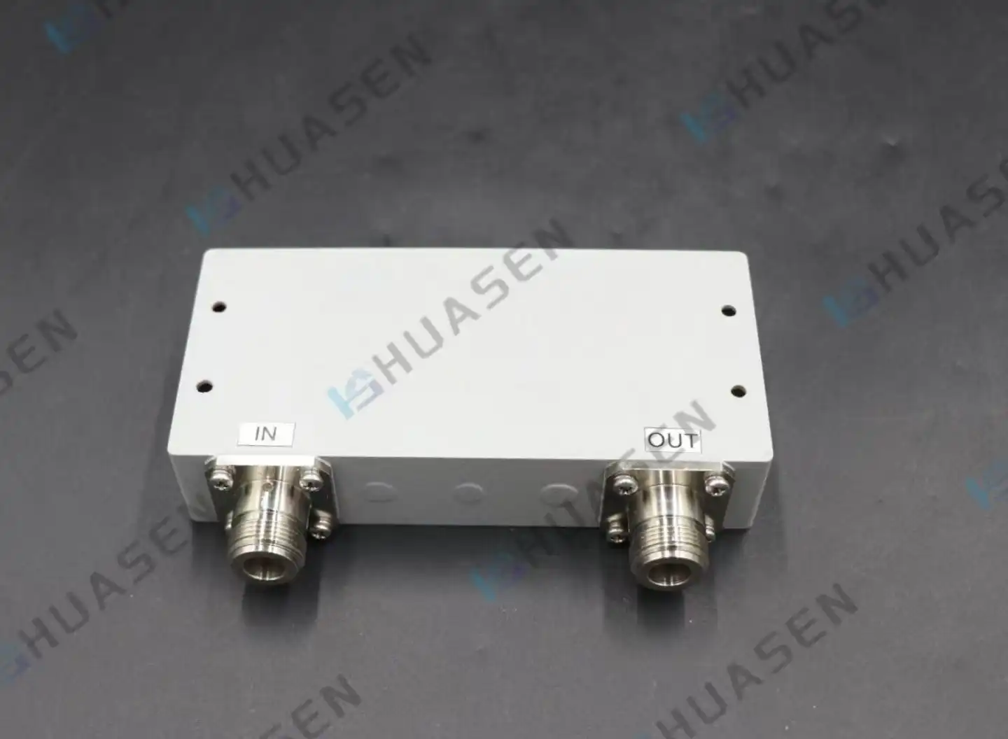
For RF systems to work at their best, they need to be able to precisely control which bands get through and which ones get stopped. This is done by a coaxial bandpass filter, which uses TEM mode transmission through solid coaxial resonators to let the desired frequency bands pass through while blocking disturbance. Insertion loss and selectivity are the two metrics that describe how well a filter works. They directly affect how well the system works and how clear the signal is. Insertion loss measures how much power is lost in the passband, and selectivity measures how well the filter can block interference from adjacent channels. For people who work in procurement in the defence and telecommunications industries, knowing how to balance these factors against size, power handling, and cost limits can make link budgets much better and lower spectral congestion in crowded spectrum environments.
Understanding Coaxial Bandpass Filters and Their Key Performance Metrics
RF system makers are always under pressure to keep signals as pure as possible while reducing the size of their components. This problem is solved by coaxial bandpass filters, which have a spread element design that works better than lumped components at microwave frequencies. Coaxial structures have empty Q-factors between 500 and 5,000, which means they have less passband noise and stronger rejection slopes than ceramic or microstrip options.
Material Selection and Its Impact on Performance
High-conductivity materials are used a lot in the construction of these devices. Most housing parts are made of precisely polished metal or brass material, which is chosen for its ability to keep heat in and electromagnetic waves out. Surface treatment is also very important. For example, silver plating lowers skin effect losses at microwave frequencies, and bronze finishes keep things from rusting when they are used outside. At Huasen Microwave, we make our filters out of metal or copper with silver-plated or oxidised surfaces. This makes sure that they will last in temperatures ranging from -40°C to +85°C. Because we chose these materials, our devices can keep their frequency stable in both warm-shore installations and Arctic-shore installations.
Performance measures are also affected by the dielectric properties of the coaxial arrangement. The Q-factor of air dielectric is the highest, but PTFE or ceramic supports make the system more stable in places with a lot of vibration, like shipboard radar systems. When building filters for aircraft uses where weight and dependability are both important, the trade-off between material permittivity and mechanical strength becomes very important.
Critical Performance Metrics Decoded
Insertion loss is the amount of power that is lost as a signal passes through a filter. It is usually measured in decibels at the centre frequency. A 0.5 dB drop in insertion loss can increase communication range by several kilometres in base station deployments. This is because it protects the system's link budget directly. The coaxial bandpass filters from Huasen Microwave have insertion loss values of ≤0.8 dB across the DC-60 GHz frequency range. This is better than the industry standard for uses that need to be as efficient as possible.
| Performance Parameter | Huasen CBPF Specification | Industry Impact |
|---|---|---|
| Insertion Loss | ≤0.8 dB | Preserves link budget, extends range |
| Out-of-Band Suppression | ≥60 dB | Eliminates adjacent channel interference |
| Q-Factor | 500-5,000 (typical) | Enables sharp selectivity transitions |
| Frequency Coverage | DC-60 GHz | Supports multi-band system consolidation |
| Power Handling | Up to the kilowatt range | Suitable for high-power transmitter chains |
The selectivity tells us how steep the change is between the passband and stopband regions. High selectivity stops transmission noise from dulling receiver front-ends, which is known as the near-far effect in cellular base stations. It is measured as a rejection curve in dB per octave. Our gadgets block out-of-band signals by more than 60 dB, which successfully separates the send and receive channels in duplexer setups.
Return loss, which is easy to forget, measures the difference in resistance at the filter ports. Signal reflections, which are caused by low return loss (high VSWR), make the system less stable and can even damage amplifier stages. Good filters keep the return loss at or below 20 dB across the passband, which keeps the formation of standing waves in coaxial transmission lines to a minimum.
Optimising Insertion Loss and Selectivity: Core Design Principles
To improve the performance of a filter, you must first understand how its physical measurements relate to its electrical properties. Both the unloaded Q factor and the coupling coefficients between cavities next to each other are controlled by the shape of the resonator. This has a direct effect on the insertion loss and the bandwidth.
Resonator Q-Factor: The Foundation of Low Loss
The unloaded Q-factor of a coaxial bandpass filter measures how well energy is stored in a resonator. Higher Q-values lower resistive losses, which means that insertion loss is lower and selectivity is better. To get a high Q, the surface roughness of the internal wires needs to be kept to a minimum. Premium filters often have manufacturing limits below a 1.6 µm Ra finish. Our precise cutting methods keep these standards and make sure that the hole sizes stay the same from one production run to the next.
Loaded Q and bandwidth are also affected by the design of the coupling system. You can change the bandwidth without having to rethink the whole filter system by using inductive coupling through eyes or capacitive coupling through probe adjustments. Because of this, it is possible to make changes so that it works for either narrowband military communications (0.5% fractional bandwidth) or wideband commercial cellular applications (10% fractional bandwidth).
Design Trade-Offs: Narrowband Versus Wideband Architectures
Narrowband filters have better selectivity, but they are more sensitive to changes in manufacturing when it comes to insertion loss. A mistake of 0.1 mm in the cutting process can change the centre frequency by several megahertz and make the insertion loss 0.3 dB higher. Wideband designs can handle less precise specs, but they need more resonator steps to keep the stopband rejection level high, which makes them bigger and costs more.
When you compare coaxial designs to other options, you can learn from the trade-offs. Even though stripline filters are small, they lose more conductor power at microwave frequencies. Waveguide cavity filters work great for high-power tasks but get too big to use below 5 GHz. When size and power handling needs come together, like in uses between 500 MHz and 18 GHz, coaxial designs are the best choice.
Advanced Tuning Techniques for Production Optimisation
After manufacturing, tuning makes up for errors that built up during mechanical assembly. By changing the volume of the cavity, mechanical tuning screws can fine-tune the passband shape and change the frequencies of each resonator. Multiple VNA measurements are needed for this process, and only skilled technicians can get the centre frequency accuracy to within 0.1% and the insertion loss to within 0.15 dB of the design targets.
For uses that need field-reconfigurable filters, hybrid tuning methods combine mechanical adjustments with electronic varactor diodes. This method is more complicated and expensive, but it makes adaptive interference reduction possible in cognitive radio systems where spectrum occupancy changes all the time.
Practical Tips for Procurement: Choosing the Right Coaxial Bandpass Filter
When choosing where to buy RF components, you have to weigh the technical ability against the cost. Instead of just copying what other companies choose for components, the design process should start with figuring out what the system-level needs are.
Translating System Requirements into Filter Specifications
Link budget analysis figures out how much insertion loss is reasonable. A sensor system with a sensitivity of -120 dBm and a noise figure of 3 dB can handle 1.5 dB of filter insertion loss before coverage drops by one cell sector. To keep intermodulation distortion from happening, transmitter chains that are close to P1dB compression need filters that can handle more than 150% of their peak working power.
Required selection is based on frequency distribution. Cellular duplexers that separate 45 MHz broadcast bands from receive bands need rejection slopes that are higher than 40 dB per octave. Broadcast combiners that join channels that are 6 MHz apart need even tighter transitions, which usually means using elliptic function designs with transmission zeros put near passband edges.
Before finalizing procurement decisions, consider these specification priorities:
- Environmental specifications must match deployment conditions. Outdoor macro cell installations require coaxial bandpass filters. Filter with IP67-rated housings with salt spray resistance per ASTM B117, while laboratory test equipment needs only benchtop RF shielding. Vibration specifications for airborne applications follow MIL-STD-810, demanding resonant frequency testing and shock resistance that indoor equipment never encounters.
- Connector standardization affects system integration costs. N-type connectors suit base station applications up to 11 GHz, while SMA connectors extend to 18 GHz with proper torque control. Military systems often specify MIL-DTL-39012 qualified connectors, adding cost but ensuring interoperability across defense supply chains.
Evaluating Supplier Capabilities and Quality Assurance
Supplier selection extends beyond product specifications to encompass manufacturing capabilities, quality systems, and technical support infrastructure. Established manufacturers like Huasen Microwave provide complete S-parameter datasets measured across temperature ranges, enabling accurate system simulations before prototype integration. Less mature suppliers may offer lower pricing but lack the measurement traceability required for qualification in aerospace or medical applications.
Certification requirements vary by application sector. Telecommunications equipment often requires RoHS compliance for hazardous substance restrictions, while defense applications mandate MIL-STD-461 EMI/EMC testing and DFARS-compliant domestic sourcing. Verification of supplier certifications prevents costly redesigns during qualification testing.
| Procurement Consideration | Off-the-Shelf Filters | Custom Designs |
|---|---|---|
| Lead Time | 2-4 weeks | 8-16 weeks |
| MOQ (Minimum Order Quantity) | 1-10 units | 50-100 units |
| Unit Cost | Higher | Lower (volume dependent) |
| Risk Profile | Low technical risk | Higher NRE investment |
| Customization Flexibility | Limited to catalog options | Tailored to exact requirements |
Custom filter designs become cost-effective beyond 100-unit volumes, particularly when standard products cannot meet simultaneous requirements for size, frequency, and power handling. Non-recurring engineering charges typically range from $5,000 to $25,000, depending on complexity, amortizing across production quantities to reduce unit costs below off-the-shelf alternatives.
Interpreting Datasheets and Performance Guarantees
Datasheet specifications require careful interpretation to avoid procurement errors. "Typical" values represent average performance across production lots but lack statistical guarantees. " Minimum" or "guaranteed" specifications define the worst-case performance that every shipped unit will meet, providing the basis for system margin analysis.
Temperature coefficient of frequency (TCF) specifications indicate how the center frequency shifts across operating temperature ranges. Aluminum housings exhibit TCF around -25 ppm/°C, requiring a ±5 MHz margin for filters operating across 60°C temperature swings. Invar resonator materials reduce TCF to -2 ppm/°C but increase cost and weight.
Passive intermodulation (PIM) specifications become critical in high-power coaxial bandpass filter transmitter applications. Third-order PIM products falling within receiver bands can desensitize base station receivers, degrading coverage. Quality filters achieve PIM performance better than -150 dBc, requiring non-magnetic materials and controlled contact surface finishes throughout the RF path.
Conclusion
Optimizing insertion loss and selectivity in coaxial bandpass filters requires balancing electrical performance against practical constraints of size, cost, and manufacturability. Procurement professionals who understand the relationships between Q-factor, resonator coupling, and material properties can specify filters that enhance system link budgets while rejecting interference. Huasen Microwave's coaxial cavity filters deliver insertion loss ≤0.8 dB and out-of-band suppression ≥60 dB across DC-60 GHz, addressing the demanding requirements of 5G infrastructure, aerospace radar, and defense communications. Proper installation practices, routine performance monitoring, and strategic supplier partnerships ensure these components deliver reliable performance throughout multi-year service lives, maximizing return on procurement investments in mission-critical RF systems.
FAQ
1. What insertion loss should I expect from quality coaxial filters?
Premium coaxial bandpass filters achieve insertion loss between 0.5 dB and 1.2 dB, depending on fractional bandwidth and frequency range. Narrowband designs (bandwidth <2%) targeting maximum selectivity may reach 1.5 dB, while wideband variants (bandwidth >10%) optimized for size reduction can exhibit 2.0 dB. Huasen Microwave's coaxial cavity filters maintain insertion loss ≤0.8 dB across our standard product line, outperforming many alternatives in efficiency-critical applications.
2. How do coaxial filters compare to microstrip designs in harsh environments?
Coaxial architectures offer superior environmental resilience compared to microstrip implementations. The enclosed metallic housing provides inherent EMI shielding and moisture protection, while microstrip designs on PCB substrates remain vulnerable to humidity absorption and temperature-dependent dielectric constant shifts. For outdoor telecommunications or military applications experiencing temperature extremes, salt spray, or vibration, coaxial construction delivers more stable frequency response and longer service life.
3. Can you provide custom frequency bands for specialized applications?
Absolutely. Our engineering team specializes in custom filter designs spanning DC-60 GHz for applications requiring non-standard frequency allocations, unique form factors, or specialized connector types. Custom development typically requires 8-12 weeks, including prototype iterations and testing, with MOQs starting at 50 units depending on complexity. Contact our applications engineers to discuss your specific requirements and receive a preliminary feasibility analysis.
Partner with a Trusted Coaxial Bandpass Filter Manufacturer
Huasen Microwave brings three decades of RF engineering excellence to every component we manufacture. Our Coaxial Bandpass Filters combine high Q-factor resonator designs with precision machining and rigorous quality control, delivering insertion loss ≤0.8 dB and out-of-band suppression ≥60 dB across DC-60 GHz frequency coverage. Whether you need off-the-shelf solutions for rapid prototyping or custom designs optimized for volume production, our engineering team provides the technical support and manufacturing capacity to meet demanding project timelines. We maintain ISO 9001 certification and MIL-STD testing capabilities, ensuring our products meet the stringent requirements of telecommunications infrastructure, aerospace systems, and defense applications. As an established supplier serving global equipment manufacturers and system integrators, we understand the procurement challenges you face—balancing performance specifications against cost targets and delivery schedules. Reach out to our technical sales team at sales@huasenmicrowave.com to discuss your coaxial filter requirements, request detailed datasheets, or obtain quotations for custom designs tailored to your system architecture.
References
1. Pozar, D.M. (2011). Microwave Engineering, Fourth Edition. Wiley, Hoboken, New Jersey.
2. Matthaei, G.L., Young, L., & Jones, E.M.T. (1980). Microwave Filters, Impedance-Matching Networks, and Coupling Structures. Artech House, Dedham, Massachusetts.
3. Cameron, R.J., Kudsia, C.M., & Mansour, R.R. (2018). Microwave Filters for Communication Systems: Fundamentals, Design, and Applications, Second Edition. Wiley-IEEE Press, Hoboken, New Jersey.
4. Hong, J.S. & Lancaster, M.J. (2001). Microstrip Filters for RF/Microwave Applications. Wiley, New York.
5. Zverev, A.I. (1967). Handbook of Filter Synthesis. John Wiley & Sons, New York.
6. Levy, R. & Cohn, S.B. (1984). A History of Microwave Filter Research, Design, and Development. IEEE Transactions on Microwave Theory and Techniques, Vol. 32, No. 9, pp. 1055-1067.
Send Inquiry