Choosing Waveguide Termination for High Power






2026-05-29 22:00:33
High-power applications require the correct waveguide termination to safeguard sensitive RF sources from catastrophic reflection damage and ensure measurement precision and system dependability. These passive components convert electromagnetic energy to heat with minimum reflection in high-frequency situations. The optimum termination fits your waveguide's characteristic impedance, minimising standing wave ratio mismatches that can damage magnetrons, klystrons, TWTAs, and solid-state power amplifiers. When designing 5G base stations, satellite uplinks, or radar calibration systems, termination specifications—power handling, VSWR, thermal management, and mechanical compatibility—help you make procurement decisions that optimise performance and minimise downtime.
Understanding Waveguide Termination Basics for High-Power Applications
To avoid damaging reflections, high-power microwave systems need precision-engineered loads. When an impedance mismatch occurs in a waveguide, RF energy reflects back to the source. Small signal deterioration may occur in low-power conditions. Reflected energy causes arcing, frequency pulling, and hardware failure at kilowatt or megawatt levels.
What Is a Waveguide Termination?
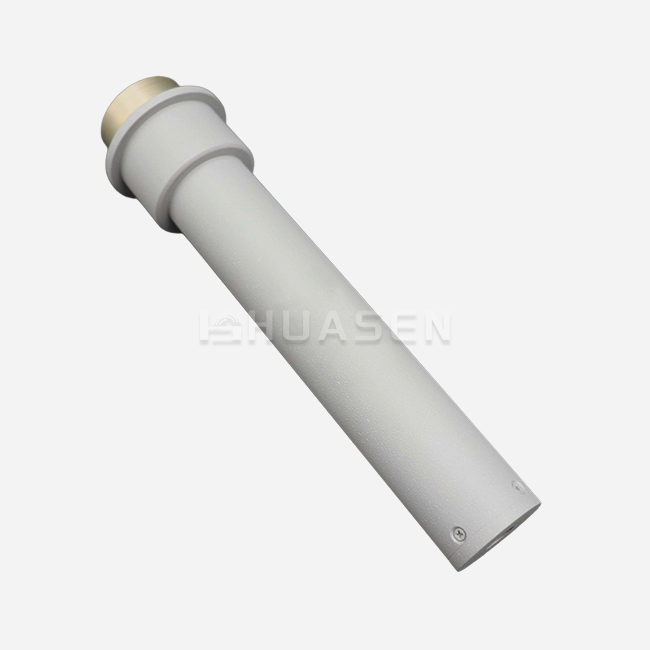
A waveguide termination, sometimes termed a matched load or fake load, absorbs electromagnetic radiation. It absorbs and thermally dissipates transmitted power, keeping the reflection coefficient near zero over the operational bandwidth. Terminations are essential for non-radiating testing, system commissioning, and calibration because they convert energy to heat. Engineers use these devices to replicate ideal antenna circumstances without disrupting actual spectrum environments or radar testing security.
Primary Functions in High-Power Environments
Waveguide terminations play three crucial functions. Absorbing energy from mismatched loads prevents retroreflection damage to costly amplifiers and tubes. They offer a known reference impedance for vector network analyser calibration, enabling precise S-parameter measurements. They allow full-power transmitter testing in production lines and laboratories without emitting signals, protecting spectrum hygiene and defence secrets.
Types of Terminations: Standard, Sliding, and Circular
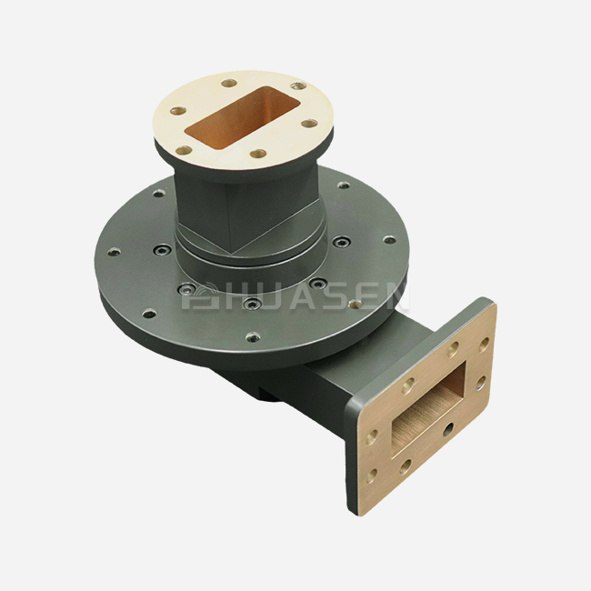
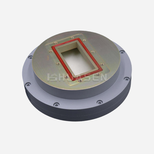
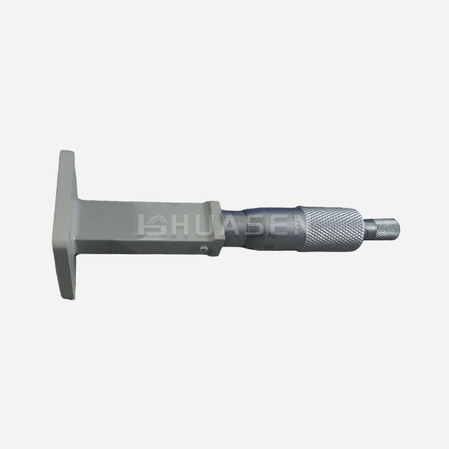
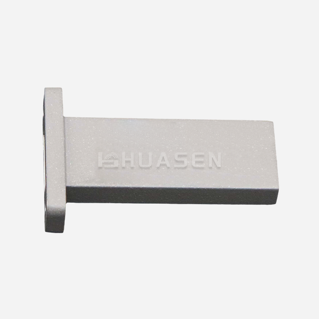
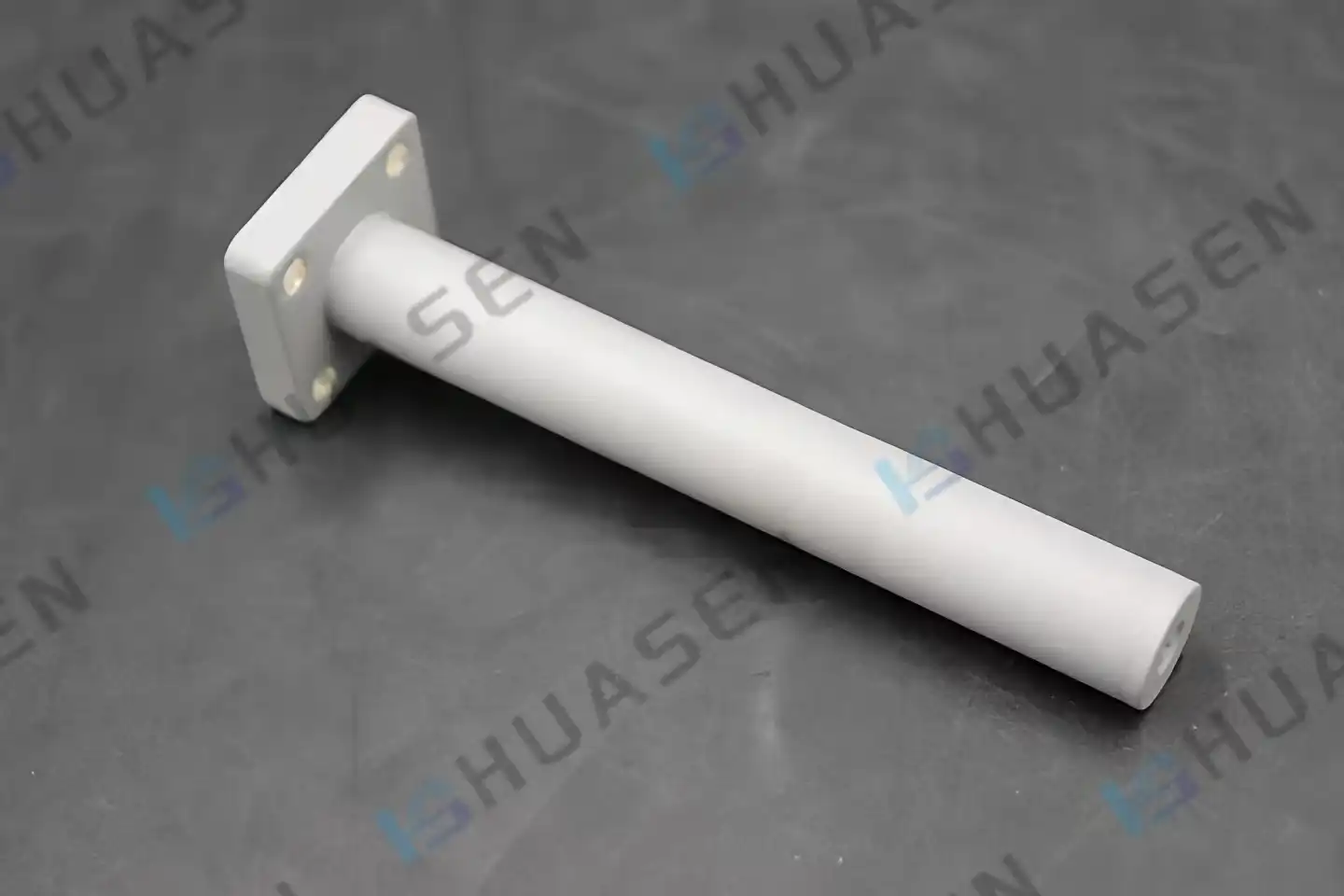
Standard absorptive loads use silicon carbide or ferrite resistive materials incorporated in waveguides for broadband performance. The longitudinally adjustable absorbing elements of sliding terminations change reflection phase while retaining magnitude. The ripple approach for high-precision VNA directivity calibration is useful at millimetre-wave frequencies where stationary loads struggle with manufacturing tolerances. High peak power pulses are handled without dielectric breakdown using circular waveguide terminations for dual-polarisation systems, rotary joints, and orthomode transducers. Based on application context, power levels, and accuracy, each kind meets procurement demands.
Comparing Waveguide Terminations: Selecting the Best Solution for High Power
Buyers may match items to operational needs by understanding waveguide termination kinds. All designs absorb RF energy, although structure, thermal capacity, and reflection differ.
Structural and Functional Variations
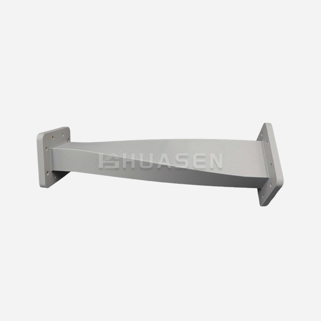
Fixed broadband loads reduce VSWR across large frequency ranges with tapered resistive films or dispersed absorbers. They are good for general testing and system protection but may not have ultra-low reflection coefficients for metrology-grade measurements. Mechanically adjustable sliding terminations allow phase-varied calibration to distinguish device reflection from measuring system faults. In satellite ground stations and airborne radar systems, circular shapes allow rotating assemblies and cross-polarisation isolation. Fusion research and industrial microwave heating require liquid-cooled variations for sustained megawatt dissipation.
Materials and Thermal Management
High-power waveguide terminations require RF-absorbent, thermally conductive materials. For pulse radar applications, silicon carbide composites have good dielectric loss tangents and heat stability up to 600°C. Despite broadband coverage, ferrite-based absorbers need careful thermal design to avoid Curie point deterioration. Aluminium housings with integrated water jackets provide continuous operation beyond 10 kW, while forced-air cooling is sufficient for intermittent duty cycles below 1 kW average power. Material selection affects power rating, operational longevity, and environmental resilience, which procurement teams evaluate when calculating the total cost of ownership.
Performance Metrics That Matter
How closely the termination fits the waveguide impedance is measured by the reflection coefficient (VSWR or return loss). High-power applications require VSWR < 1.15:1 (return loss > 26 dB) to prevent amplifier instability. Dielectric breakdown or thermal runaway occurs when peak and average dissipation capacity exceed power rating. Frequency bandwidth determines multi-band interoperability, simplifying system integrator inventory. Buyers may trust field performance since calibrated sets test these characteristics under actual environmental pressures.
How to Choose the Right Waveguide Termination for Your High-Power System?
Map system requirements to product properties to start procurement of the correct waveguide termination. Operational goals and long-term support should guide your decision criteria for updating infrastructure, prototyping new ideas, or growing production.
Matching Power Handling to Application Context
Continuous wave base station front-ends need 100-500W average power and 3:1 peak-to-average ratios. Pulse radar systems may be air-cooled since they need 10-50 kW peak power but lower average dissipation. Satellite uplink amplifiers feeding circulators need 10-20% of transmitter output terminations for antenna misalignment-reflected power. Plasma generating systems may need liquid-cooled loads over 100 kW of continuous dissipation. Understanding your duty cycle, modulation format, and failure situations ensures the termination survives worst-case conditions without degrading system capabilities.
VSWR, Insertion Loss, and Mechanical Compatibility
VSWR impacts transmitter efficiency and stability. A VSWR of 1.22:1 is sufficient for most commercial wireless, while metrology laboratories need 30 dB. Since terminations absorb all incident power, insertion loss is small, but flange quality and connection compatibility are important. Standard waveguide sizes—WR-28, WR-42, WR-90, and larger—must match transmission line specifications. In outdoor or pressured applications, UG-style, cover, or grooved flanges impact installation and seal integrity. Weight and mounting affect mechanical design, especially in aerial or shipboard applications that require space and vibration resistance.
Evaluating Supplier Capabilities
Trustworthy manufacturers provide catalogue items, application support, and customisation. Rapid prototyping speeds R&D and allows sample review before volume commitments. Experienced vendors stock common materials and equipment to reduce delivery times for bespoke frequency bands, power ratings, and environmental criteria. MIL-STD-202, ISO 9001, and RoHS compliance paperwork ensure quality and regulatory acceptability. Manufacturers like 1993-founded Huasen Microwave combine decades of waveguide knowledge with responsive engineering teams that can adapt solutions to specific system topologies.
Procurement Insights: Buying High-Power Waveguide Termination with Confidence
Performance criteria, cost frameworks, and supplier reliability must be balanced in global sourcing for a waveguide termination. Understanding how cost, certification, and customisation affect project value helps B2B buyers.
Assessing Supplier Credibility and Delivery
Test data, application notes, and peer-reviewed contributions show technical depth from reputable manufacturers, including waveguide dummy loads. Industry certifications and trade shows indicate infrastructural investment. Online platforms simplify discovery, but direct engagement shows responsiveness and engineering support. To independently check specs, request sample units with calibration certifications. Standard catalogue goods arrive within weeks, while unique designs needing new tooling may take 8-12 weeks. Transparency regarding lead times and setbacks fosters trust and realistic project planning.
Pricing Factors and Cost Optimisation
Power rating, material prices, and manufacturing precision determine pricing. Due to complicated absorber geometries, multi-octave broadband systems cost more than narrowband ones. Liquid cooling is expensive but allows high-power operation that air-cooled machines cannot. Mass manufacturing discounts reduce unit cost by 20-30% for orders over 50 items. Custom designs maximise performance and mechanical fit but require non-recurring engineering fees. Buyers should balance budget and performance with total cost of ownership—initial price, installation difficulty, maintenance intervals, and replacement frequency.
Custom Orders and Collaboration Benefits
Custom solutions solve specific problems that catalogue items cannot. A satellite ground station operator wanted dual-band terminations for C/Ku orthomode transducers with liquid cooling for -40°C to +65°C outdoor operation. Working with an experienced manufacturer produced a small package with heat management, hermetic sealing, and lightning protection that eased installation and enhanced system uptime. Partnerships that use supplier knowledge in materials science, electromagnetic modelling, and environmental testing expedite deployment and reduce risk.
Enhancing System Performance with Proper Waveguide Termination
Operational dependability requires addressing common failure mechanisms and anticipating waveguide termination technology shifts. Considering these characteristics helps procurement teams choose items with long-term value and flexibility.
Common Challenges and Failure Modes
Heat degrades absorber materials and lowers VSWR when average power exceeds dissipation capacity. Poor cooling airflow or liquid circulation increases thermal stress and premature failure. Degradation of absorbers or coatings increases reflection coefficients, which can destabilise amplifiers. Mobile platforms are susceptible to mechanical shocks, and vibration can weaken flange connections or fracture absorber substrates. Without adequate sealing and coatings, humidity intrusion, corrosive atmospheres, and thermal cycling promote material deterioration.
Optimisation Techniques and Advanced Materials
Design enhancements target thermal routes and absorption homogeneity. Finned heat sinks and induced convection boost passive cooling by 2-3x over smooth housings. Multi-stage tapered absorbers reduce peak temperature gradients by dissipating over greater volumes. Recent ceramic composites have low dielectric loss and thermal conductivity near copper, enabling compact high-power designs. Thermal imaging and time-domain reflectometry verify performance under realistic power cycling, bolstering operating margins.
Future Trends in Waveguide Technology
Integrating absorber taper profiles and cooling channels with waveguide dummy loads, additive manufacturing allows complicated designs that conventional machining cannot. Intelligent terminations with temperature sensors and RFID tags notify operators of VSWR degradation before it affects system operation. Integrating digital twins provides real-time thermal modelling and dynamic cooling parameter optimisation. These advances coincide with industry trends towards automation and remote monitoring by improving dependability and system management.
Conclusion
Selecting a waveguide termination for high-power applications requires careful consideration of power handling, VSWR, thermal control, and mechanical compatibility. Understanding fixed, sliding, and circular designs lets you match items to specific operational settings like shielding satellite amplifiers, calibrating vector network analysers, or testing radar transmitters. Supplier trust, customisation, and long-term support affect system uptime and TCO. New materials science and production methods promise dependability and intelligent integration. You guarantee your RF infrastructure performs well throughout its lifecycle by matching purchase decisions with technical requirements and future scalability demands.
FAQ
1. What is the typical lifespan of a high-power waveguide termination?
Power cycling, temperature management, and environment affect waveguide termination lifespan. Under 70% rated power, air-cooled devices endure 10-15 years with minor VSWR deterioration. Controlled liquid-cooled designs can last 20 years. Regular VSWR certification is needed due to harsh outdoor installations or thermal cycling that shorten service life to 5-8 years.
2. Can waveguide terminations be repaired or refurbished?
Absorber materials are expensive to replace, rendering terminations unrepairable. Resurfacing flanges and servicing cooling systems are possible. Manufacturer trade-in programmes recycle housings and replace absorber cores, saving 30-40% over new purchases.
3. How do I verify a termination meets its power rating?
Request calibration certificates showing operating band VSWR and thermal testing data demonstrating rated power temperature increase. Calorimetry or thermal imaging during full-power tests validates dissipation capability. Environmental resilience is assured by MIL-STD-202 or similar.
Partner with Huasen Microwave for Reliable Waveguide Termination Solutions
With over 30 years of high-frequency component manufacturing experience, Huasen Microwave provides waveguide termination devices for 5G infrastructure, satellite communications, radar systems, and RF testing settings. Our engineers work closely with customers to match power ratings, frequency bands, cooling settings, and mechanical connections to system architecture. ISO-certified methods and stringent testing techniques ensure every matched load performs consistently in real-world settings. Our worldwide supply chain and fast customer care staff can help you with rapid prototyping for R&D projects or volume manufacturing with predictable lead times. Contact our technical professionals at sales@huasenmicrowave.com to discuss your application needs, request sample units with calibration data, or get bespoke quotations from a reputable waveguide termination manufacturer dedicated to system performance and ROI.
References
1. Pozar, David M. Microwave Engineering, 4th Edition. Wiley, 2011.
2. Montgomery, C. G., Dicke, R. H., and Purcell, E. M. Principles of Microwave Circuits. MIT Radiation Laboratory Series, Volume 8. McGraw-Hill, 1948.
3. Skolnik, Merrill I. Radar Handbook, 3rd Edition. McGraw-Hill, 2008.
4. Maury Microwave Corporation. Application Note: Waveguide Termination Selection for High Power Applications. Technical Publication Series, 2019.
5. IEEE Standard 148-2017. IEEE Standard for Waveguide and Coaxial Transmission Line Assemblies for Use in Communication and Electronic Systems.
6. Collin, Robert E. Foundations for Microwave Engineering, 2nd Edition. Wiley-IEEE Press, 2001.
Send Inquiry