Best Practices for Using Antenna Near Field Measurement Probe in Labs






2026-05-14 21:42:01
Understanding how an Antenna Near Field Measurement Probe gathers electromagnetic field data in a Device Under Test's Fresnel area is the first step to near field measurement. These precision-engineered sensors collect amplitude and phase data 3 to 10 wavelengths from the antenna aperture and use Fourier algorithms to translate it into far-field patterns. These probes provide precise characterisation in tiny anechoic chambers, addressing the practical restrictions of current RF testing facilities handling enormous satellite arrays and 5G enormous MIMO systems.
Introduction
Because wireless communication systems evolve fast, antennas must be characterised before usage. The most crucial connection between hardware and data-driven performance testing is antenna near-field measurement probes. Engineers working on 5G/6G infrastructure, satellite packages, and radar systems employ these unique sensors to obtain vector field data on radiation patterns, polarisation behaviour, and beamforming precision.
This extensive handbook helps procurement managers, RF engineers, lab staff, and system designers optimise testing. Teams can make wise purchases when they understand probes, measurements, and product selection. Whether you're building a testing lab or upgrading outdated gear, these strategies will enhance measurement accuracy and save expenses. From sub-gigahertz to millimetre waves over 110 GHz. This requires careful probe design, connection standards, and environmental controls.
Understanding Antenna Near-Field Measurement Probes
Core Operating Principles
Near field probes are accurate electromagnetic sampling locations in space with well-characterised gain and phase coefficients. The wavefront form distinguishes near and distant field measurements. In the far field, wave travel is believed to be flat, whereas close field wavefronts are spherical and need phase correction. In the reactive near field (one wavelength) or spreading near field (Fresnel zone), probes detect electric and magnetic field components. These are mathematically altered to forecast their performance in the remote field without travelling far.
Probe Architecture Categories
Open-ended waveguides are most frequent in high-frequency applications due to their lower radar cross-section and improved pattern symmetry. The orthogonal feed (WOEWP) setup maintains phase centre performance over octaves. However, the Waveguide orthogonal feed Type I (WOEWPI) design improves large aperture testing directivity. COECPs function well in frequencies below 18 GHz and can cover all directions, making them ideal for circular scanning systems.
WOEWDP, dual-polarisation near-field measuring probes, can detect co-polarised and cross-polarised components simultaneously. This decreases test time in half compared to sequential single-polarisation scans. Broadband near-field measuring probes (WBOEWP) from 0.49 GHz to 112 GHz eliminate the need to swap probes during multi-band device assessment. Broadband designs achieve cross-polarisation separation above 25 dB. This is crucial for accurately measuring antenna elements in phased array systems, because element-to-element coupling affects pattern clarity.
Design Considerations and Calibration
The measuring dynamic range exceeds 60 dB, and maximum power flow is ensured when the Voltage Standing Wave Ratio (VSWR) is less than 1.5:1. Low pattern symmetry variations (< 0.1 dB) facilitate the current measuring software's probe correction algorithms. Changes above 0.5 mm produce major errors when testing electrically large antennas. Phase centre stability throughout the working band is crucial. Even in regions without climate control, the precision-machined, gold-plated aluminium structure maintains proportions.
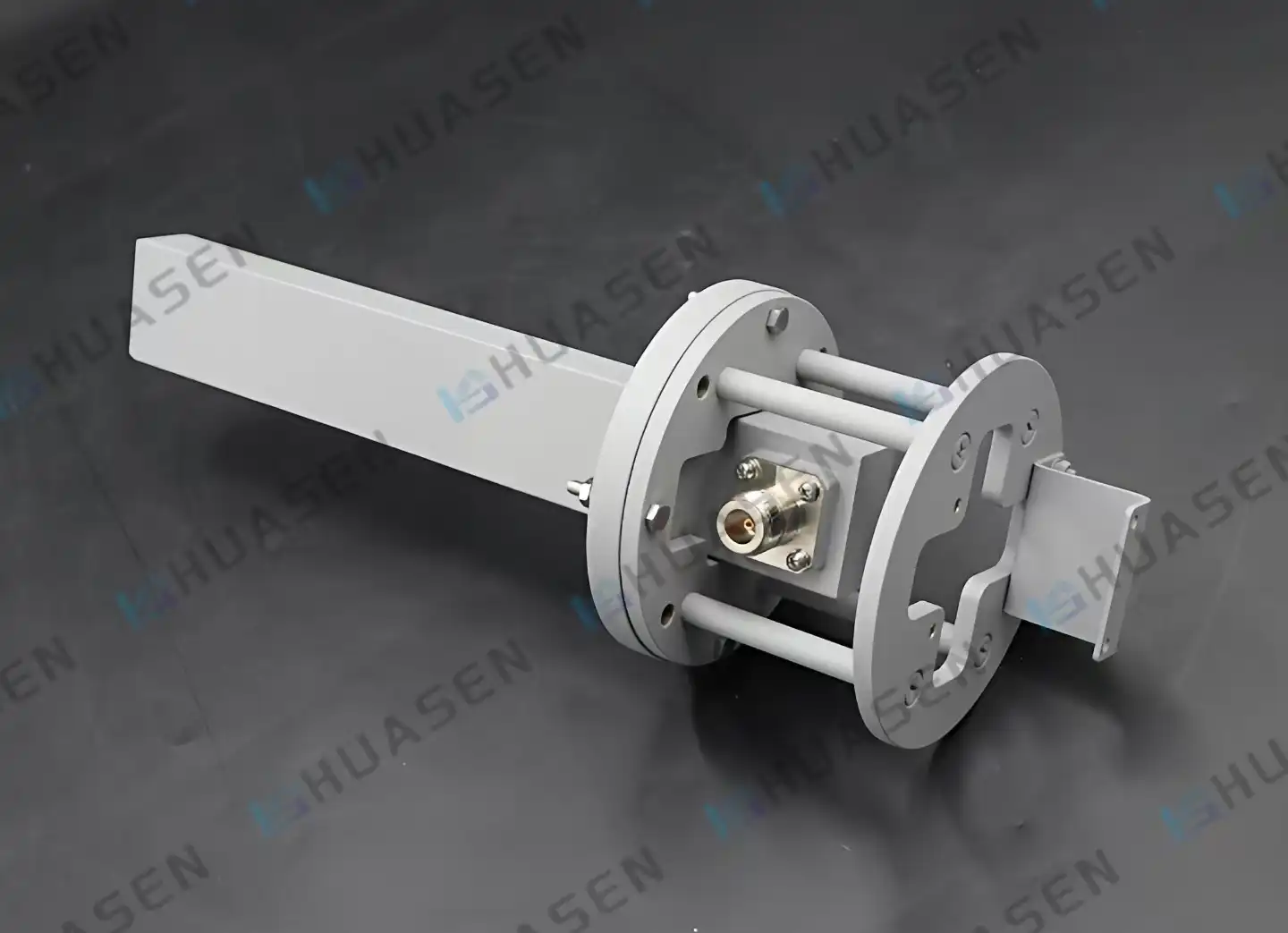
Best Practices for Conducting Near-Field Measurements in Labs
Environmental Control and Setup
Setting up a controlled measurement setting starts with getting the anechoic room ready. The material used as an absorber should have a reflection below -40 dB across the frequency range that is being used to keep multipath interference to a minimum. Stable temperatures within ±2°C stop thermal expansion that moves parts out of place. Keeping the humidity between 40 and 60% lowers the chance of electrostatic discharge, which can damage sensitive probe parts.
Precision stepper motors and optical encoders are what make sub-millimetre positional accuracy possible in probe placement systems. XY translation steps with orthogonality mistakes below 0.05 degrees are usually used in planar scanning systems. When describing high-gain satellite antennas with narrow beamwidths, spherical scanning setups are necessary because they use azimuth-elevation rotators that can resolve angles of less than 0.1 degrees.
Alignment and Calibration Protocols
Before every measurement session, the mechanical balance is checked. Laser alignment tools make sure that the lengths between the Antenna Near Field Measurement Probe and the antenna are the same as the estimated Fresnel zone requirements. Rotational axis wobble of less than 0.1 mm makes sure that the scan path can be used again and again in different test sessions. At millimetre-wave frequencies, phase mistakes of more than 5 degrees are caused by cable flexure effects. Correct cable routing with strain relief keeps measurements accurate.
There are three steps to the calibration process. Calibration of a network analyser uses precise flight standards that can be traced back to national metrology institutes to set reference planes at probe connections. Directivity, gain, and polarisation response can all be measured by probe pattern characterisation using replacement methods. End-to-end measurement accuracy is checked using reference antennas with known patterns. Uncertainties should be less than ±0.3 dB for amplitude and ±3 degrees for phase.
For operational lives of more than five years, regular maintenance plans keep probes working well. Visual inspections done once a month look for worn connectors, and VSWR checks done every three months look for damaged wire connections. Measurement tracking is kept up to date with annual recalibration against traceable standards for MIL-STD and ISO compliance paperwork.
Data Interpretation Techniques
Modern measurement software uses probe correction techniques to separate the effects of the probe pattern from the raw field data. To change from near-field to far-field, methods need sampling densities that meet Nyquist standards. For flat scans, these are usually lambda/2 spacings. When applied to the edges of the scan opening, window functions get rid of sidelobe artefacts in the patterns that are calculated for the far field.
Cross-polarisation discrimination measurements show how pure the polarisation is, which is very important for satellite data lines. To get better than 30 dB cross-pol isolation, you need probes that have 10 dB more discrimination than the goal standard. Waveguide termination feed designs (WOEWPE) work great for uses that need very pure polarisation, like defence radar systems.
Selecting the Right Antenna Near-Field Measurement Probe for Your Needs
Frequency Band and Performance Requirements
Setting the working frequency range is the first step in choosing a probe. Single-band probes work best in certain waveguide bands, like WR-10 for 75–110 GHz and WR-28 for 26.5–40 GHz. Broadband designs give up a little speed to cover more than one band without having to change the hardware. This is helpful for testing systems that use more than one frequency, like GPS and 5G devices that work together.
New 5G FR2 uses between 24.25 and 52.6 GHz can benefit from probes with standard K-connector connections (2.92 mm) or 2.4 mm connectors that can handle higher frequencies. For millimetre-wave frequencies above 60 GHz, you usually need WR-series waveguide flanges with precise alignment pins to keep the accuracy of the interface below 0.01 dB.
Evaluating Manufacturers and Specifications
Well-known companies offer a lot of information about their products, like temperature factors, directivity patterns, and the sites of the phase centres. Global companies like Keysight and Rohde & Schwarz control the high-end research market. However, smaller companies that focus on industrial testing can provide solutions that are more cost-effective.
Since 1993, Huasen Microwave Technology has been making RF components and now makes near-field Measurement Probes that work from 0.49 GHz to 112 GHz and have cross-polarisation separation of more than 25 dB. Their range of products covers a wide range of testing situations. By not having to mechanically rotate between polarisation states, the dual-polarisation Measurement Probe cuts down on the time needed for phased array validation tests. Broadband near-field Measurement Probes that cover multiple waveguide bands make it easier for labs to keep track of their supplies and meet the needs of a wide range of projects.
There are more things to think about when buying than just the original purchase price. Custom frequency ranges may have delivery lead times of 8 to 12 weeks, which can throw off project plans. The warranty should cover mechanical wear parts, like connecting contacts that have to go through many mating rounds. When troubleshooting measurement errors, quick technical help is very important—being able to talk to application engineers who know about probe correction methods speeds up the problem-solving process.
Budget Optimisation Strategies
Acquiring probes in a way that is both effective and affordable is called cost-efficient probe acquisition. Single-polarisation probes that cost less than $1000 are good for schools and small study groups that need to make simple pattern measurements. Dual-polarisation systems in the middle price range, around $3000 to $7000, offer professional-level accuracy for developing business products.
Bundled measurement kits with probes, calibration standards, and software rights offer complete solutions that have been tested and proven to work with other products from the same seller. These packages get rid of the risks of integration that come with mixing parts from different sources. Leasing turns capital costs into routine spending, which is helpful when testing needs change with the seasons or when funding is based on projects.
Applications and Case Studies of Near-Field Measurement Probes
Industry-Specific Applications
Verification of satellite payloads is the most difficult testing situation. Large synthetic aperture radar systems with apertures bigger than 5 metres need to cover flat areas that are 25 square metres in size. To reach far-field lengths, ranges would have to be longer than 10 kilometres, which is both physically impossible and too expensive. Before orbital deployment, where adjustments aren't possible, near-field scanning done in small facilities makes sure that beam-steering is accurate across all operating scan angles.
Spherical near-field systems are used to describe active antenna units for testing base station antennas for 5G infrastructure. There are hundreds of spreading elements in these phased arrays, and their feed networks are very complicated. Antenna Near Field Measurement Probe units that work at 28 GHz and 39 GHz measure the effective isotropic emitted power across three-dimensional scan areas. This information is needed to meet regulatory requirements and help network planning models predict coverage patterns.
Automotive radar sensor tuning takes care of ADAS systems that are very important for safety. Near-field probes in small antenna test areas are used to test 77 GHz radar modules on a production line, which lets more than 100 units an hour go through. Probes with low reflection coefficients are better for measuring quickly because standing waves that mess up phase readings are stopped by return loss better than 20 dB.
Measurement Challenge Resolution
A company that makes telecom equipment that is working on 5G millimetre-wave base stations ran into problems with measuring sidelobes that weren't uniform between test units. In the past, differences in results from far-field tests were thought to be caused by manufacturing errors. However, patterns that showed regular azimuthal asymmetry pointed to external factors.
Using near-field scans with high-resolution spatial sampling showed that room reflections affected the measurement, even when anechoic chamber absorber treatments were used. The managed directivity of the near-field probe kept unwanted signals away from the antenna being tested, and spatial filtering after processing got rid of any remaining contamination. Measurement accuracy went from ±1.5 dB to ±0.3 dB, which made it possible to confidently qualify for production and cut scrap rates by 12%.
Emerging Trends
Robotic location and AI-driven anomaly spotting are both parts of automated measurement systems. Machine learning algorithms that have been trained on validated antenna patterns can spot measurement outliers that need to be reviewed by a human. This speeds up test cycles while keeping quality standards. Near-field testing can now be done in non-traditional shapes thanks to custom probe designs that are made to fit specific antenna layouts, like conformal arrays on aeroplane fuselages and marine SATCOM domes.
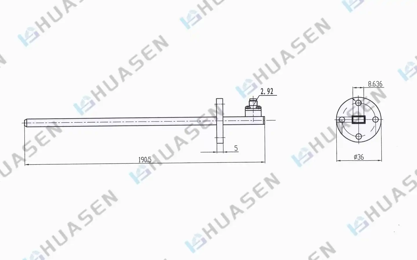
Troubleshooting and Avoiding Common Pitfalls
Common Misconceptions
Specification errors happen when people mix up how to understand near-field and far-field facts. Near-field amplitude distributions don't directly show far-field patterns; transformation methods with probe adjustments are still needed. When teams move from far-field facilities to near-field facilities, they don't always expect the same numerical results. They forget that near-field readings record phase information that allows for more detailed analysis, but needs to be properly processed mathematically.
Another misunderstanding has to do with the distances needed for measurements. Putting tools close to antennas for no reason doesn't make them more accurate or more efficient. The best scan distances combine the Fresnel zone sampling density with the realistic dynamic range limits. If you are too close, the signal levels get too high and overload receivers, and if you are too far away, the coupling isn't strong enough, and the signal-to-noise ratios get worse.
Error Sources and Corrections
Antenna Near Field Measurement Probe misalignment is the main mistake that can be avoided. When testing a 30 dBi antenna, a misalignment of 1 degree causes pattern changes that are more than 0.5 dB. Fixtures that hold probes in place must be able to handle scanning accelerations without breaking. Alignment stability is confirmed by using reference points to check it on a regular basis.
Environmental electromagnetic radiation messes up readings in places that don't have the right protection. Sensitive receivers pick up cellular signals, Wi-Fi networks, and close emitters. Spectrum tracking before measurement campaigns finds contaminated frequency bands that need to be fixed by bandpass filtering or rescheduled for times when there is less activity.
Systematic mistakes that can't be found without reference standards build up over time due to missed calibrations. By taking part in inter-laboratory comparison programmes and making measurements traceable, system performance can be checked against that of other facilities. By keeping records of calibration events, software versions, and setup settings, documentation practices make it possible to figure out what's wrong months after the data was collected.
Personnel Training and Procedures
The quality of the measurements is directly related to how skilled the person is. Training programmes that cover electromagnetic theory, probe features, and how to use software help reduce mistakes made by users. Standardised operating procedures write down step-by-step instructions for everything from setting up the machine to storing the data. This makes sure that all workers and shifts follow the same rules.
Modern measurement systems offer technology that reduces the need for human control, but it is still necessary. Automated processes can't fix basic setup mistakes like entering the wrong frequency, orienting the antenna's polarisation in the wrong way, or connecting the cables incorrectly. Failures in measurement campaigns that cost a lot of money can be avoided by using checklists and peer review before starting long scan sequences.
Conclusion
To use near-field measurement tools effectively, you need to combine technical know-how with strict processes and high-quality equipment. Cross-polarisation isolation probes that work from 0.49 GHz to 112 GHz make it possible to characterise a wide range of antenna systems in a small space. By choosing the right probe structures, like orthogonal feeds, dual-polarisation designs, or broadband setups, testing goals can be met. Using environmental controls, calibration methods, and best practices for data analysis guarantees accurate measurements that allow for a confident product launch. Near-field measurement methods are still very important for developing and validating antennas, even as wireless technologies move towards higher frequencies and more complex designs.
FAQ
1. What frequency range should I specify when ordering a near-field probe?
Match the frequency range of the probe to the working bands of your antenna plus 10%. For checking 5G FR2 between 24.2 and 29.55 GHz, make sure the probe can work between 22 and 32 GHz. Broadband probes let you test across multiple bands, but make sure the cross-polarisation works well across the whole range, since some designs lose performance at the edges of bands.
2. How often should near-field probes undergo calibration?
Traceability for compliance paperwork is kept up to date with annual testing. Use reference antennas to find performance drift every three months for temporary proof. After physical impacts, damaged connectors, or fixes that affect RF signal routes, the device needs to be recalibrated right away. Extreme temperatures or humidity in the environment may speed up ageing, which means that you need to check your age more often.
3. Can a single probe handle different antenna sizes?
The probe's usefulness depends on how the antenna's measurements compare to its wavelength, not just its size. For small antennas like PCB patches, small probes work well, but for big aperture arrays, directivity-minimising probes are needed to cut down on measurement time. By getting rid of polarisation rotation patterns, dual-polarisation probes cut test times in half for all antenna sizes. Talking to Antenna Near Field Measurement Probe providers about specific antenna sizes and frequency bands is the best way to make sure you choose the right probe.
Partner with Huasen Microwave for Precision Near-Field Measurement Solutions
Reliable antenna characterisation demands proven measurement technology backed by responsive technical support. Huasen Microwave Technology delivers near-field measurement probes engineered for demanding RF testing environments. Our product range—spanning orthogonal feeds, dual-polarisation probes, and broadband configurations—covers 0.49 to 112 GHz with cross-polarisation isolation exceeding 25 dB. Standard connector options, including K, SMA-K, and 2.92-K, ensure compatibility with existing test systems.
As a trusted Antenna Near Field Measurement Probe manufacturer since 1993, we combine decades of waveguide expertise with modern manufacturing precision. Our engineering team provides application support throughout probe selection, system integration, and measurement optimisation. Whether you're validating 5G base stations, satellite packages, or radar sensors in cars, our solutions deliver measurement confidence supporting successful product deployment. Contact our specialists at sales@huasenmicrowave.comto discuss your testing requirements and request detailed specifications tailored to your laboratory's unique needs.
References
1. IEEE Standard for Definitions of Terms for Antennas (IEEE Std 145-2013), Institute of Electrical and Electronics Engineers, 2014.
2. Yaghjian, Arthur D., "An Overview of Near-Field Antenna Measurements," IEEE Transactions on Antennas and Propagation, Vol. 34, No. 1, January 1986, pp. 30-45.
3. Johnson, R.C., Ecker, H.A., and Moore, R.A., "Compact Range Techniques and Measurements," IEEE Transactions on Antennas and Propagation, Vol. AP-17, No. 5, September 1969, pp. 568-576.
4. Parini, Claudio, Gregson, Stuart, McCormick, John, and Jansen van Rensburg, Daniël, "Theory and Practice of Modern Antenna Range Measurements," Institution of Engineering and Technology, London, 2nd Edition, 2020.
5. Schennum, Gerald H., "Planar Near-Field Antenna Measurements," Antenna Measurement Techniques Association Conference Proceedings, Atlanta, Georgia, October 1995.
6. Hansen, Jørgen Bach, "Spherical Near-Field Antenna Measurements," IET Electromagnetic Waves Series 26, Institution of Engineering and Technology, London, 1988.
Send Inquiry