
Bend Waveguide for Compact RF Layouts






2026-05-15 23:34:57
Engineers always have to figure out how to get high-frequency signals through smaller and smaller enclosures without lowering performance when they're making current RF systems for things like radar, satellite communications, and telephones. A bend waveguide is a beautiful answer because it lets you change the direction of electromagnetic waves very precisely while keeping low insertion loss and high signal integrity. When it comes to microwave and millimeter waves, flexible coaxial wires lose a lot of their signal strength. But these precision-machined parts keep the signal strength even when room is limited. Understanding the features and uses of Bend Waveguides is important for getting the best system performance, whether you're putting parts into a 5G base station front-end, a satellite payload, or a flying radar module.
Understanding Bend Waveguides and Their Role in Compact RF Layouts
Modern radio frequency (RF) and microwave devices need parts that work very well while taking up less space. This need is met by bend waveguides, which allow controlled changes in the direction of electromagnetic energy while keeping the transmission properties that make waveguide technology better than other high-frequency connection methods.
What Makes Bend Waveguides Essential in RF Design?
A bend waveguide sends electromagnetic waves along a bent path while keeping the basic mode structure the same, which is usually TE10 in rectangular waveguides. This skill is very important for system builders who have to work around structural hurdles, connect ports that aren't lined up right, or fit parts into chassis shapes that aren't straight. Because it can handle high power levels while keeping the phase stable, the part is essential in many situations, from medical linear accelerators to satellite earth stations.
The actual form of these parts changes depending on what they are used for. The bigger diameter of rectangular waveguides is changed by H-plane bends that happen along the plane that is parallel to the magnetic field vector. When set up correctly, this setup reduces mode change and reflection to a minimum. On the other hand, E-plane bends the curve along the electric field plane, which needs careful radius control to keep modes from getting excited when they shouldn't.
Key Design Parameters That Influence Performance
The bend radius is the most important design element that affects how well a waveguide works. To keep reflection and mode distortion to a minimum, engineers usually ask for radii that are larger than two wavelengths at the working frequency. When bends get tighter, they cause impedance changes that show up as higher VSWR and insertion loss. Choosing the right material is also very important. For example, oxygen-free high-heat-conductivity copper works great for electricity, and aluminum alloys are lighter for uses in space where every gram counts.
The quality of the surface finish has a direct effect on how the loss behaves. When the frequency goes above Ka-band, the skin's depth disappears, so surface roughness plays a big role in absorption. Plating with silver or gold lowers these losses and protects against rust. To make sure it works, the thickness of the plating must be more than three times the depth of the skin at the highest working frequency.
Understanding Loss Mechanisms in Curved Waveguides
When electromagnetic field patterns change shape during direction changes, this is called bending loss. Sharp slopes bring the energy of the force field closer to the walls of the waveguide, which makes the metal surfaces lose more resistance. If the modes don't meet at the bend surfaces, energy can be reflected back toward the source. This lowers VSWR and the power that is sent. Manufacturing flaws cause scattering losses. Impedance changes happen in specific areas where the surface isn't smooth, or the dimensions don't meet specifications.
Precision manufacturing methods make these loss processes less noticeable. Computer numerical control (CNC) machining keeps the size differences between pieces to a few microns, and electroforming methods make bends that are smooth and don't have any mechanical parts that could cause gaps. Manufacturers of good products list both the average and the highest loss values across the entire operating bandwidth. This lets system designers be sure of their worst-case performance estimates.
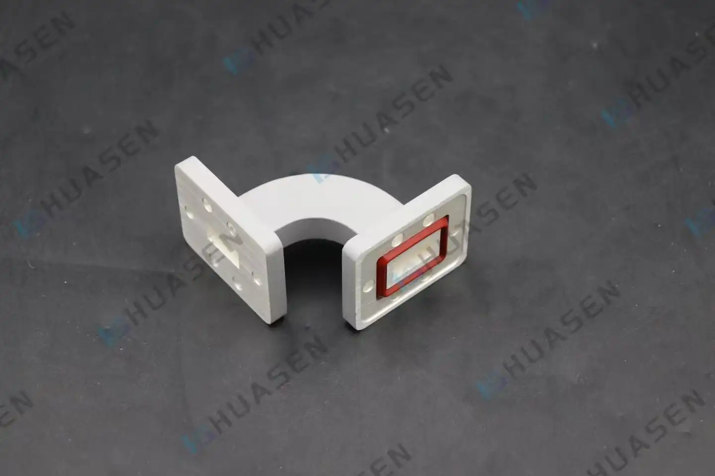
Comparing Bend Waveguides to Straight Waveguides: Making the Right Choice
Before choosing between bend waveguides and straight waveguides, you need to look at a number of factors that affect both the system's short-term success and its long-term dependability. This choice affects not only the electricity features but also the mechanical integration, thermal management, and ease of upkeep, considering Bend Waveguide.
Performance Metrics That Drive Component Selection
Straight waveguides have the lowest insertion loss, which is usually between 0.01 and 0.05 dB per foot and depends on the frequency and cross-section. When radii are bigger than what is suggested, properly built bend waveguides often add less than 0.1 dB of extra loss per bend. When you compare Bend Waveguides to the many straight parts and flanged links needed to make the same routing path with only linear components, this performance gap gets a lot smaller.
There is a lot to learn about impedance matching from VSWR standards. The VSWR of high-quality bend waveguides stays below 1.10:1 across their entire bandwidth, which is the same as that of premium straight parts. The important thing is how precisely the parts are made, because any change in size in the bent part causes localized resistance changes that reflect energy. Reliable makers give approved test data that shows how well each production unit performs in terms of VSWR, not just average values from testing prototypes.
Rigid Versus Flexible Solutions for Different Applications
Rigid bend waveguides, which can be made by electroforming or milling solid metal blocks, offer the best mechanical stability and power handling. These parts can handle the vibrations that come with installing things on airplanes and the changes in temperature that satellite packages go through. Because the geometry stays the same, the products always work the same way electrically. This makes them the best choice for defense and aircraft uses where dependability can't be sacrificed.
Flexible waveguides are easy to install and can be adjusted mechanically or by expanding or contracting due to temperature changes after the initial assembly. But they have more insertion loss (usually between 0.5 and 2.0 dB per foot) and can't handle as much power. The flexible inner surface's ribbed design causes changes in resistance that spread electromagnetic energy around. When the ease of use is more important than the speed, these parts are good for labs and business systems.
When Alternative Routing Solutions Make Sense?
In integrated photonic circuits, where sizes are measured in microns instead of millimeters, ring resonators and photonic waveguide bends are used for specific tasks. These parts can't handle the high amounts of power or harsh conditions that are common in RF and radio systems. Coaxial cable systems let you choose how the cables are routed, but they lose too much signal above 20 GHz, so they can't be used for millimeter-wave uses. It's up to system engineers to fit the technology of the parts to the needs of the application. Bend waveguides work best where high power, low loss, and mechanical rigidity all come together.
Design, Simulation, and Fabrication Techniques for High-Performance Bend Waveguides
To build Bend Waveguides that meet strict requirements, you need advanced technical tools and manufacturing methods. Knowing these methods helps people who work in procurement figure out what suppliers can do and what standards are needed for custom designs.
Optimizing Bend Radius and Geometry for Minimal Loss
The connection between bend radius and loss is based on well-known mathematical models that have been proven to work through decades of study and real-world use. Increasing the radius lowers field distortion but takes up more room, which is a basic choice in small RF setups. Engineers use optimization methods to balance these different needs while taking into account the limits of manufacturing and the tolerances for assembly.
Elliptical bends are useful in some situations where room limitations are different along orthogonal directions. The changing curve keeps the mode pure while fitting into bands that are not symmetric. Computer-aided design tools can model these complicated shapes and predict how they will work before making an expensive sample. The simulation results help choose the radius, find the best wall thickness, and place the flanges so that the goal specs are met.
Simulation Tools That Reduce Development Risk
With great accuracy, finite-difference time-domain methods describe how electromagnetic waves move through curved objects. These simulations show how the fields are spread out, find possible mode conversion problems, and guess the scattering parameters across frequencies. Engineers make changes to designs online, trying out different parameter values that would be too expensive to make in real life.
Beam propagation methods are great at describing gradual changes, which makes computations faster for smooth turns like e-bend waveguides, where field changes happen slowly. Finite Element Method tools can work with complicated material interactions and any shape, which makes them useful for designs that use dielectric loading or composite building. Complex development programs use more than one modeling method and check the results against each other to make sure they are reliable before they start making the product.
Materials and Manufacturing Methods for Production-Scale Deployment
Silica and silicon are used a lot in photonics, but they aren't strong enough or able to handle enough power for microwave systems. Aluminum alloys, especially 6061, are easy to machine, conduct electricity well enough, and are light enough for aircraft weight limits. When you're near the water, where salt spray is a constant threat, brass is the best metal for rust protection. The temperature range, dynamic stress, and surface treatment suitability must all be taken into account when choosing a material.
Integrated circuits use lithography and etching to make waveguide structures on a microscale level. RF and microwave parts need to be machined, electroformed, or cast based on how many need to be made and how well they need to work. Automated checking systems are used in high-volume manufacturing to make sure that important measures are correct without the errors that come with measuring by hand. These quality controls make sure that each batch is the same, which is very important for system designers who buy hundreds or thousands of units.
Manufacturers that sell to businesses offer a wide range of customization options. Customers and engineering teams work together to make standard designs fit certain frequency bands, flange types, power levels, or environmental requirements. This gives companies more options, which speeds up the development of new products while using tried-and-true designs that lower technical risk. Quick-turn prototyping services make sure that unique designs work before they are made in large quantities. This lowers the risk of buying and speeds up time-to-market.
Practical Applications and Benefits of Bend Waveguides in Compact RF Layouts
Knowing where Bend Waveguides offer real benefits helps engineers and procurement workers explain why they should be chosen over other options. In the real world, deployments show how well speed and dependability work in demanding apps.
Telecommunications Infrastructure and 5G/6G Networks
Base station front-ends put more features into weatherproof cases that are placed on towers and roofs. To get around power sources, cooling systems, and structure supports, waveguides running from transceivers to antenna arrays have to go in a lot of different directions. These links can be made with H-plane bends and E-plane bends, which keep the low loss that is needed for system sensitivity and send power efficiency. The stiff construction can handle wind loads and weather changes that would damage flexible options.
Backhaul links that use E-band frequencies (71–76, 81–86 GHz) need communication lines with very low loss. When built correctly, a bent waveguide adds less than 0.15 dB of insertion loss per bend. This protects the link budget for the wireless transmission line, which is where it provides range and throughput. The precision flanges make sure that connections are made the same way every time, and they keep working even after many installation and repair rounds.
Satellite Payloads and Space-Qualified Systems
Communication satellites use waveguide networks to send data from traveling-wave tube amplifiers to output multiplexers. These networks have to be able to handle launch vibrations, heat, vacuum, and years of use without any upkeep. Aluminum alloy bend waveguides that have been covered with silver give the needed performance within tight mass budgets. Since there are no flexible parts, there are no possible failure modes that could happen from repeated bending during tests on the ground and during launch.
In S-bend designs, the input and output ports are spaced apart. This meets the thermal management needs of separating amplifiers that generate heat from filters that are sensitive to temperature. The waveguide design keeps the phase stable even when the temperature in geostationary orbit changes a lot, from direct sunlight heating to eclipse shadow cooling. This steadiness is very important for multi-channel systems because phase relationships affect how well signals are combined.
Radar Systems and Electronic Countermeasures
Fire control radars in the air send high-power bursts from solid-state amplifiers to gimbaled antenna arrays that scan over large angles. The fixed emitter is connected to the spinning joint by double-bend waveguide assemblies. These keep the electrical performance while allowing for mechanical motion. The building can handle the noise from jet engines and weapons being used, as well as the G-forces that happen during battle moves.
Multi-bend designs are used in ground-based air monitoring radars to send power from a central transmitter to antenna parts that are spread out. The waveguide network keeps the phase relationships that are needed for beamforming while directing paths around the antenna pedestal's structural parts. At flanged connections, environmental plugs keep out water that could hurt performance or cause corrosion in coastal systems.
Real-World Performance Data
In a recent rollout of a satellite communications terminal, rigid multi-bend systems and an H-bend waveguide were used instead of bendable waveguide interconnects. In the 27.5–31 GHz uplink band, the measured insertion loss went down by 1.2 dB, which directly led to more link cushion. Based on accelerated life tests, the better VSWR decreased stress on the amplifier, which increased the average time between failures by 40%. System integrators saw instant cost savings from fewer transmit power needs and better long-term dependability.
These benefits add up across all system designs. By optimizing routing, you can save space and improve integration density, which makes the container smaller and lighter. Better signal route freedom makes mechanical design easier and speeds up the development process. Engineers choose Bend Waveguides for tough RF uses because they have good electrical performance, are strong mechanically, and can be designed in a variety of ways.
Conclusion
Bend Waveguides are a great way to solve important routing problems in small RF layouts where performance can't be sacrificed, even though room is limited. The technology provides low insertion loss, good VSWR, and high power handling ability in packages that are mechanically strong and can handle harsh environmental conditions. These parts are used in 5G infrastructure, satellite communications, radar systems, and medical tools to keep the security of signals as they travel through complicated transmission lines. To choose the right provider, you need to look at their technical skills, the quality of their products, how flexible they are with customization, and their support services that go beyond just delivering products. Companies that put in the time and effort to understand what their customers want and offer full tech support become valued partners instead of just transactional suppliers.
FAQ
1. What factors most significantly influence bending loss in waveguide designs?
Bending loss is mainly affected by bend radius, operating frequency, surface roughness, and plating quality. Tight bends increase field concentration and resistive loss, while manufacturing precision is critical to avoid impedance mismatches and signal scattering.
2. Can bend waveguides be customized for unique RF layout requirements?
Yes. Manufacturers can customize bend angles, radii, flange types, mounting options, and protective features to match specific RF requirements. Electromagnetic simulations and rapid prototyping help verify performance before mass production.
3. How do rigid bend waveguides compare to flexible alternatives in harsh environments?
Rigid bend waveguides provide stable electrical performance under extreme temperatures and vibration, with higher power handling than flexible designs. While they offer better reliability, they are less adaptable during installation because routing must be planned in advance.
Partner With a Trusted Bend Waveguide Manufacturer
Huasen Microwave Technology has helped RF system makers all over the world by providing high-precision waveguide components that meet the strictest requirements. As a vertically integrated manufacturer, we can do everything from electromagnetic design to cutting, finishing, and final testing. This means that we can guarantee consistent quality and short lead times. We have been a Bend Waveguide seller for a long time, so we keep a large stock of standard designs and can quickly make changes for unique uses. Our engineering team has the technical know-how and production ability to help you succeed, whether you're making next-generation 5G infrastructure, satellite payloads, or defense systems. Email us at sales@huasenmicrowave.com to talk about the needs of your project, get full datasheets, or set up a sample review. We're ready to show you why Huasen Microwave is the waveguide component partner of choice for top system designers in the defense, aerospace, and telecommunications industries.
References
1. Marcuvitz, Nathan. "Waveguide Handbook." MIT Radiation Laboratory Series, Vol. 10, McGraw-Hill, 1951.
2. Balanis, Constantine A. "Advanced Engineering Electromagnetics," 2nd Edition, Wiley, 2012.
3. Pozar, David M. "Microwave Engineering," 4th Edition, Wiley, 2011.
4. Saad, Theodore S. "Handbook of Microwave Integrated Circuits," Artech House Microwave Library, 1985.
5. Collin, Robert E. "Foundations for Microwave Engineering," 2nd Edition, IEEE Press, 2001.
6. Montgomery, C.G., Dicke, R.H., and Purcell, E.M. "Principles of Microwave Circuits," MIT Radiation Laboratory Series, Vol. 8, McGraw-Hill, 1948.
Send Inquiry
You may like
