Coaxial Power Combiner Behavior Under High-Frequency Load Stress






2026-07-22 17:04:08
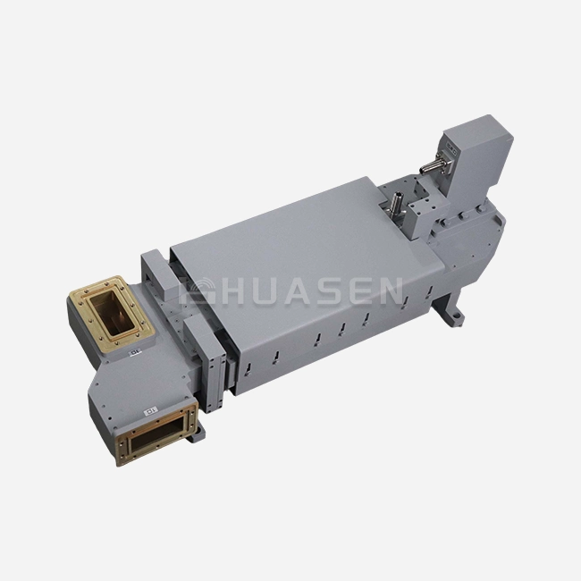
When operating under high-frequency load stress, a coaxial power combiner experiences critical behavioral changes that directly affect system reliability and signal integrity. These passive RF components, which sum multiple input signals into a unified high-power output, face challenges including thermal buildup, insertion loss degradation, and impedance mismatch when subjected to intense power loads and rapid signal fluctuations. Understanding how these devices respond under stress conditions is essential for engineers and procurement specialists working in radar, 5G infrastructure, and satellite communication systems where performance cannot be compromised.
Understanding Coaxial Power Combiners and High-Frequency Load Stress
Operating Principles of RF Signal Combining
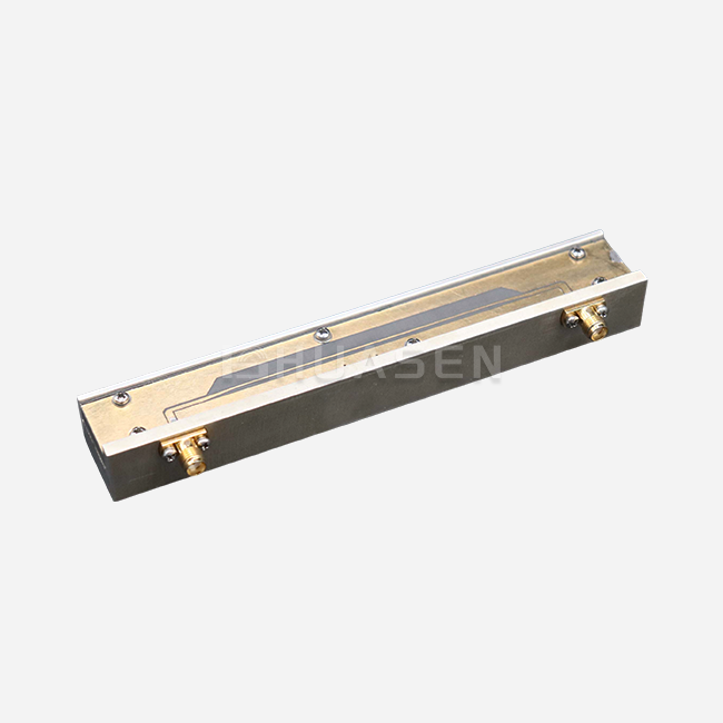
Coaxial power combiners work by adding up the RF energy from several amplifier modules using carefully planned transmission line networks. The coaxial architecture, on the other hand, uses concentric conductor arrangements that protect communications from outside interference and can handle much higher power levels. To stop reflections that waste energy and create heat, the device keeps the characteristic impedance (usually 50 ohms) the same across all ports to prevent energy waste.
Defining High-Frequency Load Stress
There are several problems that happen at the same time in high-frequency load stress that test the limits of a component. Peak power surges, continuous wave operation at full ratings, quick changes in temperature, and mismatched load conditions all speed up wear. When used in base stations at 3.5 GHz or millimeter-wave frequencies close to 40 GHz, even small design flaws become more noticeable. When electrical stress and thermal cycles work together, they can cause failure modes that standard testing might not reveal.
Critical Role in B2B RF Infrastructure
System designers who are putting together 5G macro cells or phased array radar systems need to combine networks in order to reach their output power goals. Reliability under load stress is a must because a single failed combiner can shut down an entire transmit chain. We've seen procurement teams ask for more and more devices that have been through long-term burn-in tests and specific thermal performance data before they approve vendor names.
Root Causes of Performance Issues Under High-Frequency Load Stress
Signal Integrity Degradation Mechanisms
As frequency goes up and power levels stress internal parts of a coaxial power combiner, insertion loss goes up in a way that can be measured. When impedance matching isn't perfect at connection points, voltage standing wave patterns are made that send energy back to the input ports. This reflected power not only makes things less efficient, but it also makes isolation resistors too hot for their intended use. Over 10 GHz, when current concentrates in thinner and thinner layers on the surface of conductors, skin effect losses become more noticeable. Any difference in phase between the input channels, even if it's only 5 degrees, leads to incomplete vector addition, which turns RF energy into waste heat instead of combined output power.
Thermal Stress and Material Limitations
Isolation resistors and circuit losses lose power, which creates hot spots in certain places that make materials grow at different rates. The solder joints between transmission line parts are put under a lot of mechanical stress when the temperatures change from -40°C in the winter to +85°C during the summer. As the temperature rises, the loss tangent values of the dielectric materials that support the inner wires change, which makes the performance even worse. We looked at field returns from marine communication systems where salty humidity sped up rust at connector interfaces, making high-resistance paths that would sometimes appear and cause catastrophic arcing when the power was on full.
Comparative Technology Assessment
The following table shows how the success of different combining methods compares:
| Technology Type | Power Handling | Insertion Loss (dB) | Bandwidth | Thermal Management |
|---|---|---|---|---|
| Coaxial Wilkinson | 500W–2kW | 0.2–0.5 | 1–18 GHz | Good |
| Radial Line Combiner | 5kW–50kW | 0.1–0.3 | 2–40 GHz | Excellent |
| Waveguide Combiner | 10kW–100kW | 0.05–0.15 | 8–40 GHz | Superior |
| Hybrid Coupler | 100W–1kW | 0.3–0.8 | 0.5–26.5 GHz | Moderate |
Waveguide systems work best in situations with a lot of power, but they need to be installed in bigger spaces and be perfectly aligned mechanically. Coaxial designs and coaxial power combiners strike a good mix between being small and being able to handle enough power for most radar and telecommunications uses.
Optimizing Coaxial Power Combiners for High-Frequency Load Conditions
Advanced Material Selection Strategies
Modern designs go beyond the usual brass construction by using silver-plated copper metals that can conduct heat better than 380 W/m·K. Low-loss PTFE dielectrics with dissipation factors below 0.0002 keep the signal pure even when the temperature inside gets close to 150°C. Isolation resistors no longer use wirewound substrates but instead use thick-film ceramic substrates. This spreads heat over a larger surface area and stops failures from happening in just one place. These material upgrades directly fix the cases of thermal runaway that we've found in older systems.
Precision Manufacturing Impact
Controlling tolerances at the micron level makes sure that the impedance stays the same across the whole joining network. VSWR stays below 1.15:1 across operating bandwidths covering multiple octaves thanks to computer-controlled machining of the transmission line dimensions. Before devices leave the factory, automated testing stations make sure that the phase balance is within ±3 degrees and the amplitude matching is better than ±0.3 dB. This strict production process leads to field reliability that meets the MIL-STD-202 standards for shock and vibration for radar systems in the air.
Thermal Management Implementation
When you add aluminum heat spreaders with an anodized surface treatment to bare housings, they let 40% more heat escape. Materials at the thermal interface that have a conductivity rating of more than 5 W/m·K effectively move heat from isolation resistors to surfaces on the outside. We put in place forced-air cooling channels in high-density base station layouts that keep junction temperatures 30°C below critical levels even when the stations are running at full power all the time. Case studies from satellite ground stations that work in deserts show that good temperature design can increase the average time between failures to more than 100,000 hours.
Validation Through Real-World Data
Longer burn-in protocols that keep devices running at 110% of their rated power for 168 hours straight find flaws that weren't seen in regular acceptance testing. Measurements of passive intermodulation that show performance better than -155 dBc make sure that sensitive receiver chains in full-duplex communication systems can work with the system. By changing the temperature between two extremes and watching the S-parameters in real time, changes in the thermal coefficient that could lead to field failures can be found. This thorough method of validation gives procurement teams faith in the stability of the supply chain in the long run.
Comparing Coaxial Power Combiner Solutions for High-Frequency Applications
Technology Trade-Off Analysis
When choosing between combining topologies, you have to weigh a lot of different performance factors against budget and space limitations. Power dividers can work both in parallel and backwards for combining and splitting functions, but they are not as good at isolating as dedicated coaxial power combiner designs. Hybrid couplers naturally separate signals by using quadrature timing, but they add 3 dB of theoretical loss to two-way combination setups. Waveguide systems handle power better than any other method and lose it much less, but they need to be carefully put together mechanically and take up a lot more rack room.
Coaxial designs are the most common type of telecoms infrastructure because they offer the best value for money when power levels range from 500W to 5kW per output port. The enclosed structure shields electromagnetic fields better than open stripline designs, which is very important for keeping interference at bay in environments with a lot of devices. Standard port compatibility, which includes N-type, SMA, and 2.92mm connections, makes it easier to integrate systems without having to make special cables.
Supplier Landscape Evaluation
Established companies like Mini-Circuits serve the laboratory and low-power instrumentation markets with catalogue Coaxial Power Combiner products that can be delivered quickly but can't be changed much. Pasternack has a large collection that covers a wide range of frequencies, but it may not be able to make changes to meet specific military or aircraft needs. Niche suppliers that focus on high-power broadcast and radar uses usually have higher minimum order numbers but offer technical help for custom solutions.
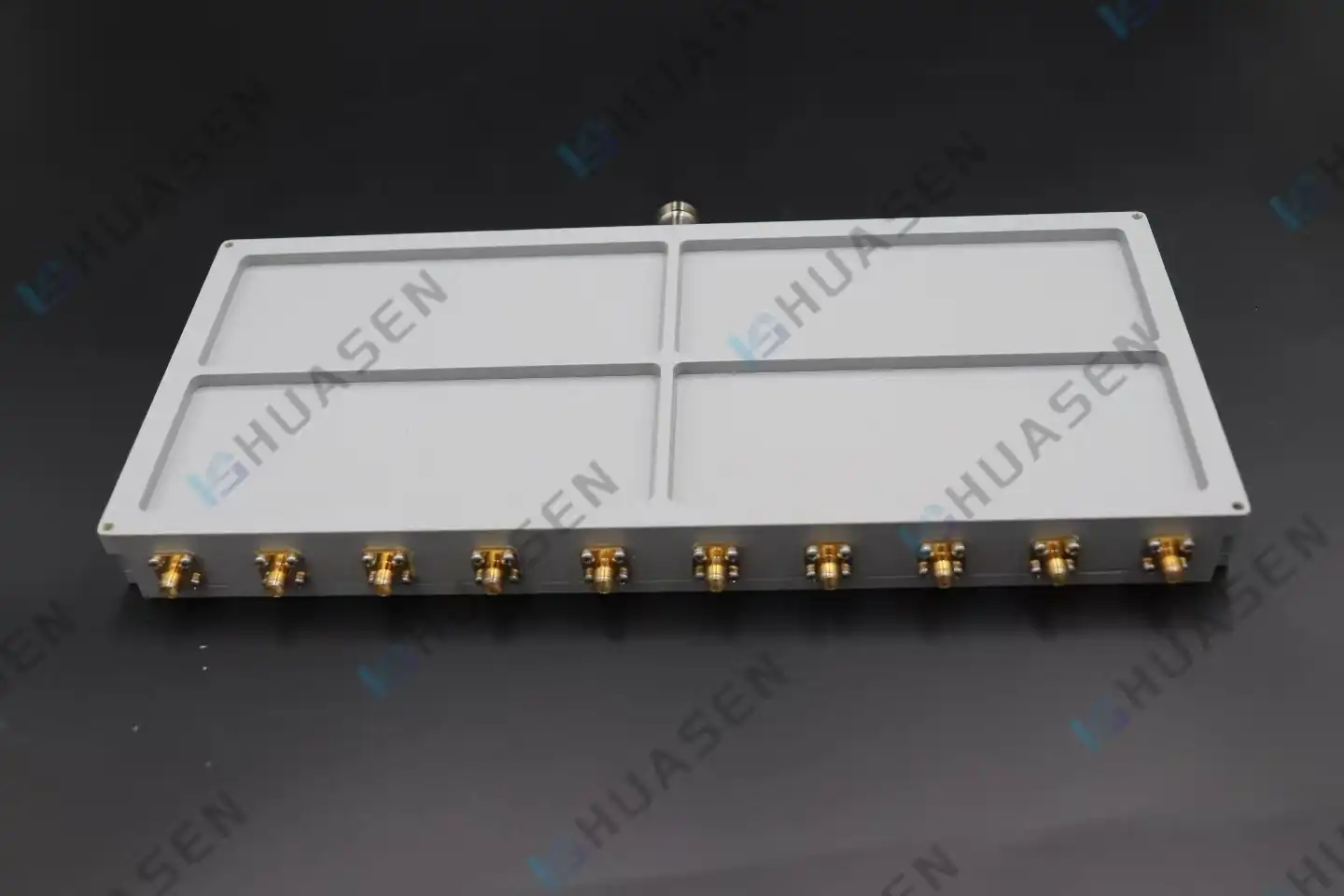
Huasen Microwave is in a unique position in this market because it has thirty years of experience in RF technology and can make a wide range of products. Our Radial Line Combiner technology is very stable from DC to 40 GHz, which directly meets the wide bandwidth needs that telecommunications system designers have when combining different frequency bands into a single infrastructure. Because splitting ratios range from 1:2 to 1:10, it's not necessary for equipment makers to keep a lot of different kinds of parts in stock.
Structured Selection Criteria
The following table of parameters helps with buying decisions:
| Specification | 5G Base Station | Phased Array Radar | Satellite Uplink | Broadcast Transmitter |
|---|---|---|---|---|
| Frequency Range | 3.3–4.2 GHz | 8–12 GHz | 14–14.5 GHz | 88–108 MHz |
| Power per Port | 200W | 500W | 1kW | 5kW |
| VSWR Requirement | <1.25:1 | <1.20:1 | <1.15:1 | <1.10:1 |
| Isolation | >20 dB | >23 dB | >25 dB | >20 dB |
| Environmental | IP65 | MIL-STD-810 | Space-qualified | NEMA 4X |
By matching component specs to application needs, you can avoid over-engineering, which drives up costs, and make sure that there are enough performance gaps for long-term dependability.
Procurement and Support Considerations for High-Frequency Coaxial Power Combiners
Strategic Sourcing Approaches
When you work directly with a manufacturer, you can use their engineering tools during the planning phase, which lets you fine-tune your specifications before committing to large production runs. Online wholesalers are convenient for small sample orders, but they might not have enough technical knowledge to help you figure out problems with integration. Not only should unit prices be discussed in bulk negotiations, but so should consignment inventory arrangements that protect against problems in the supply chain without tying up working capital.
Customization and Lead Time Factors
Catalogue items usually ship within a few days, but they don't always meet the exact needs of a system in terms of connector types, mounting setups, or power rates. Engineering validation processes for custom designs last between 4 and 8 weeks, and production lead times add another 6 to 12 weeks, based on how complicated the design is. Before agreeing to large orders, asking for, for example, units to be tested for environmental qualification lowers the risk of design changes being made at the last minute that cause project schedules to slip.
Technical Documentation Utilization
Full datasheets should have full two-port S-parameter files that were measured at different temperatures. This lets you do an accurate simulation of the whole system before you add the hardware. Tolerance callouts on mechanical drawings make container design and heat modeling easier. Installation instructions that include torque requirements for connector interfaces keep things from breaking during assembly and make sure that the electrical contacts work properly.
Partnership Value Beyond Transactions
When mixing devices that interact with amplifier modules that have load-pull sensitivities, suppliers who offer application engineering support can help solve problems with impedance matching. Coaxial power combiner calibration data that can be linked to national standards helps people believe performance claims and supports paperwork needed to meet legal requirements. After-sales service that is quick to respond and includes failure analysis for field returns finds the root causes and keeps the product getting better.
Conclusion
A thorough knowledge of thermal physics, material science, and RF design principles is required to manage coaxial power combiner behavior under high-frequency load stress. As frequencies get closer to millimeter waves and power levels push component limits, problems like insertion loss, impedance matching, and heat loss get worse. Modern combiner designs are reliable enough to meet the strict needs of 5G infrastructure, radar systems, and satellite communications. They do this by carefully choosing the materials they use, manufacturing them with great care, and making sure that their heat management is tested and proven. To be successful in procurement, you need to work with manufacturers who can provide the engineering depth, customization flexibility, and long-term supply chain stability that mission-critical RF systems need.
FAQ
1. How does high-frequency load stress specifically damage coaxial combiners?
Long-term use at full power levels creates heat in isolation resistors and conductor joints, which leads to solder reflow, dielectric loss, and oxidation of connection plating. When two different materials don't expand or contract at the same rate, mechanical stress builds up and cracks spread. When loads aren't balanced, they cause high VSWR conditions that reflect power back into the device. This doubles the thermal stress at connection points and could lead to catastrophic arcing.
2. What performance margins should be specified when designing systems?
To keep junction temperatures within safe limits, conservative engineering practice says that combiners should only be run at 70% of their rated continuous power. Setting the VSWR performance 20% higher than the ideal system needs protects against changes in the environment and components that are getting old. To keep amplifiers from interacting during load transients, isolation standards should be 5 dB higher than the minimum requirements.
3. Can existing combiners be upgraded to handle higher stress levels?
Adding better thermal interfaces and external heat sinks can increase the amount of power that can be handled by 15 to 25 percent without making any changes to the inside. Thermal margins are increased by switching isolation resistors to ceramic types with higher wattages. For major changes, the plant has to redo work to switch dielectric materials and replate wires, which usually makes buying new cheaper than refurbishing.
Partner With Huasen Microwave for Reliable High-Frequency Power Combining Solutions
Huasen Microwave has a track record of solving difficult problems related to high-frequency load stress using cutting-edge radial line combiner technology that works from DC to 40 GHz. Our adjustable splitting ratios—1:2, 1:3, 1:4, 1:8, and 1:10—work with a wide range of system designs without having to keep extra material on hand. Standard connectors like N-type, SMA, 2.92mm, and 5339 make sure that the integration goes smoothly. As a well-known company that has been making coaxial power combiners for 30 years and has a reputation for excellence in RF engineering, we offer full support from initial specification consultation to production validation and troubleshooting in the field. Get in touch with our applications engineering team at sales@huasenmicrowave.com to talk about how our ability to handle high power and our ability to be customized can help you make the best radar, phone, or satellite communication system design.
References
1. Bahl, I. J., & Bhartia, P. (2003). Microwave Solid State Circuit Design (2nd ed.). Wiley-Interscience, Chapter 9: Power Combining and Dividing Networks.
2. Collin, R. E. (2001). Foundations for Microwave Engineering (2nd ed.). IEEE Press, Section 7.4: High-Power Combiners and Thermal Considerations.
3. Matthaei, G. L., Young, L., & Jones, E. M. T. (1980). Microwave Filters, Impedance-Matching Networks, and Coupling Structures. Artech House, Chapter 14: Power Divider and Combiner Design.
4. Pozar, D. M. (2011). Microwave Engineering (4th ed.). John Wiley & Sons, Section 7.2: Power Dividers and Combiners Under Load Mismatch.
5. Seymour, R. A., & Horton, M. C. (1975). "Analysis of Radial Line Power Combiners for High-Power Applications." IEEE Transactions on Microwave Theory and Techniques, 23(12), 982-989.
6. Wilkinson, E. J. (1960). "An N-Way Hybrid Power Divider." IRE Transactions on Microwave Theory and Techniques, 8(1), 116-118.
Send Inquiry