Antenna Mounting Options for Telecom and RF Applications






2026-07-23 16:47:06
When discussing antenna mounting for telecom and RF applications, we're addressing the precision-engineered structural systems that mechanically couple RF transmission elements to towers, rooftops, or mobile platforms. Proper antenna mounting directly influences signal propagation, system longevity, and operational efficiency across 5G networks, satellite links, and radar installations. The selection process involves evaluating load-bearing capacity, environmental resilience, adjustability features, and compatibility with existing infrastructure. Understanding these mounting options allows procurement professionals and system integrators to optimize network performance while controlling total cost of ownership and minimizing deployment risks in challenging operational environments.
Understanding Antenna Mounting Basics for Telecom and RF Applications
More than just physical steadiness is determined by the mechanical contact between an antenna and the structure that supports it. This link impacts the integrity of the signal, the ease of upkeep, and the dependability of the system when it is exposed to external stress. Working with telecom infrastructure for 30 years, we've seen how making more choices affects performance measurements and network uptime.
Defining Core Mounting Functions
In engineering, professional mounting assemblies are used for more than just attaching things. They keep accurate azimuth and elevation angles, which are needed for accurate beamforming in large MIMO deployments. The assemblies soak up vibration energy that would damage sensitive RF electronics otherwise, especially when used on the go or in places with a lot of wind. Managing corrosion is important when connecting metals that are not the same, like aluminum antenna housings to galvanized steel towers. Isolation seals are needed to stop galvanic degradation.
Common Mounting Configurations Across Industries
Different operating situations call for different mounting methods. Non-penetrating ballasted mounts are usually used for rooftop setups in cities to keep the structure from changing and to reduce the risk of water getting in. Wall-mounted setups work well for small cell deployments where space and style issues limit what can be used. Pole-mounted assemblies are most common in rural macro-cell sites because they are higher and can cover the whole area. For marine use, special gear devices are needed that can adjust to the pitch and roll of the ship while keeping the satellite link stable.
Safety and Structural Considerations
Installation safety is more than just protecting workers; it also includes making sure the structure will last for a long time. When figuring out wind loads, you have to take into account both the amount of ice that forms and the speed of the winds, which in coastal areas often exceed 150 mph. The tools for mounting should meet the TIA-222-H guidelines, which say how much weight it can hold based on the type of terrain it is in. Lightning can damage equipment, but using the right grounding techniques and corrosion-resistant fasteners will keep the connections strong for as long as the installation is in use.
Choosing the Right Antenna Mount for Your Application
To choose the right mounting gear, you have to look at a lot of technical and practical factors. The choice affects the costs of initial deployment, ongoing maintenance, and the overall performance of the system. We've helped hundreds of installers through this process by matching fitting solutions to the needs of each application.
Adjustable versus Fixed-Mount Architectures
Using precision-threaded hardware, like Grade 8.8 or A325 fasteners, adjustable mounts let you tilt and swivel the device in any direction. This adaptability is very helpful when optimizing the network and coverage patterns need to be fine-tuned. On the other hand, it adds to the complexity of the mechanism and could come loose when vibrated, so lock screws or nylon-insert lock nuts are needed. Fixed mounts are better because they are more rigid and need less maintenance. This makes them perfect for permanent installations where coverage patterns have been carefully modeled and proven. The choice depends on whether your distribution plan values initial optimization flexibility more than long-term upkeep simplification.
Material Selection Impact on Performance
Durability, weight, and RF openness of the antenna mounting are all directly affected by the material's makeup. ASTM A572 Grade 50 high-tensile strength steel is great for heavy sector antennas because it can hold a lot of weight, but it needs to be hot-dip galvanized according to ASTM A123 standards to keep it from rusting. Marine-grade stainless steel (316 alloy) is resistant to chloride attack in coastal installations, but it costs 40–60% more than galvanized steel to buy. Aluminum alloys are lighter for rooftop uses where structural load limits apply, but they need to be carefully separated from steel support structures to stop galvanic corrosion.
Environmental Adaptation Requirements
Different mounting features are needed for different operational settings. Offshore platforms need to be made of 316 stainless steel and have extra passivation processes to make them resistant to salt spray. In the desert, installations need a UV-resistant powder coating to keep the paint from fading from the sun's strong rays. For operations in the Arctic, materials must be tested at -40°F to make sure they won't break during high-temperature cycling. By knowing your placement area, you can choose the right protective treatments and material types.
Top Antenna Mounting Solutions and Hardware Options in 2026
Today's fastening technology is the result of decades of work in the field and improvements in engineering. New solutions combine the ability to handle a lot of traffic with the ease of installation, using what has been learned from deploying networks around the world.
Professional-Grade Mounting Assemblies
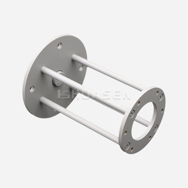
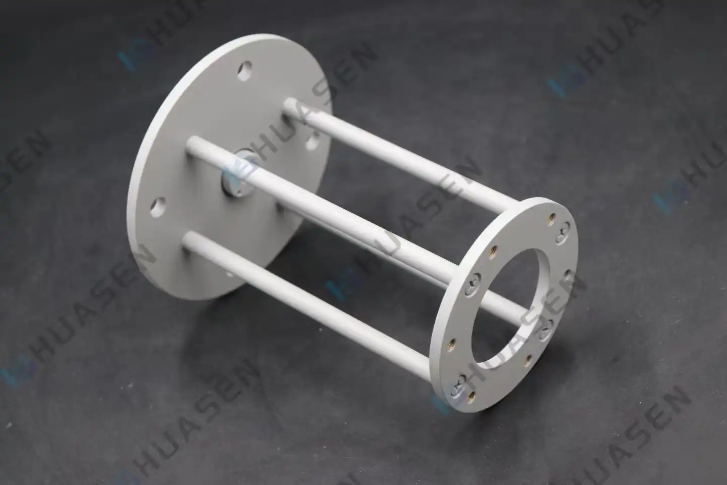
Huasen Microwave Technology has made custom mounting assemblies that are perfect for microwave labs, system installations, and deployments in the field. There are both L-type and I-type bracket configurations in these assemblies. Each is best for a different set of space limitations and load distributions. Precision-machined parts make up the device for adjusting the height. This lets you set the angle of the tool precisely without it moving. Dual-polarized antennas are common in modern MIMO architectures, and the ability to adjust the polarization makes them work. The small footprint also keeps support structures from getting too much wind load.
| Specification | Small Series | Medium Series | Large Series | Extra-Large Series |
|---|---|---|---|---|
| Load Capacity | Up to 15 kg | 15-35 kg | 35-60 kg | 60+ kg |
| Elevation Range | 0-90° | 0-90° | 0-90° | 0-90° |
| Azimuth Range | 360° continuous | 360° continuous | 360° continuous | 360° continuous |
| Material | Galvanized Steel | Galvanized Steel | Stainless Steel Option | Stainless Steel |
| Wind Survival | 120 mph | 130 mph | 150 mph | 160 mph |
Universal Compatibility Features
Modern mounting gear has common connection points that work with all antenna footprints and tower shapes. Adjustable throat clamps can fit pipe diameters from 1.5 inches to 6 inches, so you don't need any adapter kits to install them. The spacing between the mounting holes is normal in the industry, so they will work with antennas from a number of different makers. System designers who manage a wide range of tools at many client sites can simplify their inventory by making it more universal.
Specialized Mounts for Challenging Environments
For some uses, fixing options that are specifically made are needed. For setups on mobile vehicles, you need shock-absorbing spring bases that keep the antennas from shaking when the vehicle moves and maintain electrical ground continuity. Aerospace-grade aluminum and composite materials are used to make aircraft and UAV mounts lighter. Quick-release mechanisms make it easy to set up and take down temporary setups quickly, which is useful for emergency contacts or field testing.
Installation Best Practices and Common Mistakes to Avoid
Correct construction methods separate systems that work well for a long time from ones that break down too soon. We've written down installation methods that cut down on launch time while increasing the reliability of the system.
Step-by-Step Installation Methodology
Start by doing a full site survey, making sure the structure can handle the load, and looking for possible sources of RF interference. Gather the tools you'll need, such as thread-locking compounds, precise torque wrenches, and digital inclinometers for checking angles. Attach the bracket assembly to the support structure, making sure that all of the screws meet the torque requirements set by the maker. For main attachment bolts, these are usually 40 to 50 ft-lbs. Place the antenna on the mounting plate and route the cables so that they are not in the way of wind resistance or mechanical stress. Use compass bearings and inclinometer readings to do the initial alignment. Then, use a spectrum analyzer to fine-tune by measuring the received signal strength.
Critical Errors That Compromise Performance
The most common antenna mounting fitting mistake is not tightening bolts enough, which lets wind-driven vibrations slowly loosen connections. This causes the parts to become out of line, which leads to mechanical failure during bad weather. When wires enter the antenna box, they can be loaded with wind and put under extra mechanical stress if they are not managed properly. If you don't add anti-seize powder to stainless steel threads, they will gall, which is a form of cold welding that makes it very hard to make changes without destroying the threads. If you skip the last step of verifying the orientation, systems will work with less-than-ideal signal levels, which will lower network capacity and dependability.
Maintenance Protocols for Long-Term Reliability
Set up inspection plans for important projects every three months to check the tightness of the fasteners, the state of the cables, and the accuracy of the alignment. Galvanized coatings should be checked for zinc loss every year during rust checks, especially in industrial or marine settings. Record baseline performance metrics as soon as the system is installed. This will make it easier to spot trends of degradation during routine maintenance. Any fasteners that show signs of corrosion or mechanical damage should be replaced because faulty hardware can cause the antenna to lose all of its signal during a storm.
| Maintenance Task | Frequency | Critical Parameters | Acceptance Criteria |
|---|---|---|---|
| Fastener Torque Check | Quarterly | 40-50 ft-lbs primary bolts | Within 10% of specification |
| Alignment Verification | Semi-Annual | Azimuth ±2°, Elevation ±1° | Meet link budget requirements |
| Corrosion Inspection | Annual | Zinc coating thickness | >60 microns remaining |
| Cable Condition | Annual | Jacket integrity, connector seal | No cracks or water ingress |
Procurement Guide: How to Source Antenna Mounting Equipment Efficiently?
Strategic procurement matches the short-term needs of a project with the long-term dependability of the supply chain. Buyers who are good at their jobs look at providers in more ways than just the price per unit.
Assessing Supplier Capabilities
Full technical paperwork, such as load calculations, material certifications, and compliance statements for relevant standards, is how qualified providers show their engineering depth. Precision machining, welding that meets AWS D1.1 standards, and good surface treatments should all be part of a manufacturer's skills. Lead times for regular goods are usually between 2 and 4 weeks, but based on how complicated they are, custom designs may take 6 to 8 weeks. How quick a supplier is during the quote process is often a good indicator of how well they will help with production and service after the sale.
Balancing Quality and Total Cost of Ownership
The initial buy price is only one part of the total cost. Premium fastening gear that is more resistant to rust means that it doesn't need to be replaced as often, which lowers the overall cost over its lifetime, even though it costs more up front. Sticking to a single supplier's line of products makes training easier, cuts down on the need for extra parts, and speeds up repair processes. When you buy in bulk from a trusted manufacturer, you can save 15 to 25 percent on costs and get priority production slots during busy deployment times.
Evaluating Technical Support Infrastructure
Full supplier support includes engineering help before the sale for custom applications, quick sample delivery for fit testing, and documentation of calibration data for quality checks. Respondent after-sales service is very important when installation help or help with fixing problems is needed in the field. Suppliers who offer design advice can help users find the best antenna mounting solutions for their needs. This could lower the cost of hardware while also increasing performance by matching specs more closely.
Conclusion
Mechanical needs, environmental factors, and operational goals must all be carefully considered when choosing an antenna mounting option. The mounting interface has a direct effect on the data quality, the dependability of the system, and the cost of upkeep over the life of the placement. Modern mounting kits are the result of decades of technical progress. They offer features like adjustability, sturdiness, and compatibility that make placement easier and ensure long-term performance. Procurement professionals can get the most out of their investments in telecom and RF infrastructure while minimizing technical and operational risks by learning the basics of mounting, avoiding common installation mistakes, and working with skilled suppliers.
FAQ
1. What factors determine optimal antenna mounting height?
The ideal antenna mounting height is based on the coverage needs, the terrain, and the need to reduce interference. Line-of-sight range is extended by higher sites, which is important for microwave backhaul lines, but they cost more and are more likely to be damaged by wind. In cities, lower heights may be needed to keep path loss from building entry to a minimum. Most of the time, regulations set maximum heights near airports or in residential areas.
2. How do I ensure mounts withstand hurricane-force winds?
Choose mounting gear that meets TIA-222-H standards for the wind zone and terrain exposure type that you have. Make sure that the wind survival rates take into account the amount of ice that will form in your area. Fasteners don't come loose when they are installed correctly with calibrated torque wrenches and thread-locking compounds. Inspections done on a regular basis find early signs of mechanical wear and tear before they become catastrophic.
3. Can mounting assemblies accommodate non-standard antenna configurations?
Manufacturers with a good reputation offer customization services for special uses. When it comes to specific dimensions, load distributions, and interface requirements, Huasen Microwave can make mounting solutions that fit. For proper engineering analysis and manufacturing, custom designs usually need thorough antenna drawings and descriptions of working parameters.
Partner with Huasen Microwave for Superior Antenna Mounting Solutions
Every mounting unit that Huasen Microwave makes is based on our more than 30 years of experience in RF engineering. Our carefully designed brackets can be used for a wide range of installs, from small lab sets to tough outdoor jobs in harsh circumstances. Different types of antennas can be used with the changeable elevation systems, which keep the mechanical rigidity needed for stable signal propagation. As a well-known company that provides antenna mounting, we can fully customize the dimensions, load capacities, and interface specifications of our brackets to meet the exact needs of your project.
Our engineering team works directly with system designers to help with design and provide technical documentation that speeds up the buying and deploying processes. Before it is shipped, quality assurance procedures make sure that every assembly meets strict standards for load-bearing and rust protection. Contact our experts at sales@huasenmicrowave.com to talk about your specific mounting problems and get detailed technical advice based on decades of proven performance in the field.
References
1. Telecommunications Industry Association. (2018). TIA-222-H: Structural Standard for Antenna-Supporting Structures and Antennas. Arlington: TIA Publications.
2. American Welding Society. (2020). AWS D1.1/D1.1M: Structural Welding Code—Steel. Miami: AWS Technical Standards.
3. ASTM International. (2019). ASTM A123/A123M: Standard Specification for Zinc (Hot-Dip Galvanized) Coatings on Iron and Steel Products. West Conshohocken: ASTM Standards.
4. Rappaport, T. S. (2021). Wireless Communications: Principles and Practice (3rd ed.). Upper Saddle River: Prentice Hall.
5. Balanis, C. A. (2016). Antenna Theory: Analysis and Design (4th ed.). Hoboken: John Wiley & Sons.
6. International Electrotechnical Commission. (2017). IEC 60721: Classification of Environmental Conditions. Geneva: IEC Publications.
Send Inquiry